00194614-08 Trainingsdoku. SG X-Serie_X4i SW70x (AL2)_EN.pdf - 第333页
TwinHead Settings Description of Boards on the Tw inHead 333 Student Guide SIPLACE X-Serie and X4I SW70x (AL2) Description of LEDs H2-H9 The voltage monitors trigger as soon as the target voltage is e xceeded or under sh…
TwinHead
Description of Boards on the TwinHead Settings
Student Guide SIPLACE X-Serie and X4I SW70x (AL2) 332
Legend
Head Adapter for TwinHead (SX4 with HCU)
9.4.1.2 Head Adapter for TwinHead (SX4 with HCU)
The head adapter board connects the head interface from the bottom side directly. The main boards of
TwinHead segment 1 and 2 are connected directly via 2 flat ribbon cables, each. This head adapter must
be changed for head modularity, if you use a C&P head.
Head adapter for TwinHead
Legend
1 Connector Z axis Twin segment 1 4 Connector Z axis Twin segment 2
2 Connector D axis Twin segment 1 5 DIP Switch (without function)
3 Connector D axis Twin segment 2 6 LED C167 = ON TQM Module on the head
interface C500 --> OK
PP1 Boot CAN processor Twin segment 1 PP2 Boot CAN processor Twin segment 2
PP1 Reset CAN processor Twin segment 1 PP2 Reset CAN processor Twin segment 2
NOTICE
The flat ribbon cable sets are different for TwinHead segment 1 and 2.
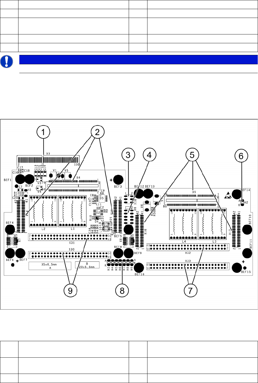
1 X3 Connection to the head interface board
C700
6 LED H2
2 X4, X14, X15 Connector for HCU1 7 X32-X33 Flat ribbon connection for
segment 2
3 X18 CAN bus test connector for HCU1/2 8 LED H3-H9
TwinHead
Settings Description of Boards on the TwinHead
333 Student Guide SIPLACE X-Serie and X4I SW70x (AL2)
Description of LEDs H2-H9
The voltage monitors trigger as soon as the target voltage is exceeded or undershot by 5%.
Base Ada pter for TwinHead (SX1/2 s eries)
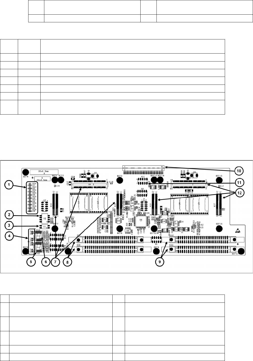
9.4.1.3 Base Adapter for TwinHead (SX1/2 series)
The Base Adapter PCB (Part Number 03055517-xx) has the same purpose as the Head Adapter that is
used on the X series machines. If head modularity is performed and the TwinHead exchanged for
another head type, then the Base Adapter PCB must also be exchanged.
Legend
4 X6 Programming connector for FPGA 9 X30-X31 flat ribbon connection for segment
1
5 X9, X16, X17 Connector for HCU2
H2 RS232 Shines when the programming connector for the HCU is connected, see DIP switch
setting at the head interface.
H3 1V5 Voltage monitor 1.5 V, shines red in event of errors.
H4 3V3 Voltage monitor 3.3 V, shines red in event of errors.
H5 5V Voltage monitor 5 V, shines red in event of errors.
H6 15V Voltage monitor 15 V, shines red in event of errors.
H7 DP Voltage monitor DP (currently without function)
H8 24V Voltage monitor 24 V, shines red in event of errors.
H9 LOC Voltage monitor local, shines red as soon as one of the voltage monitors triggers (not
for 24 V)
1 LED H1-H9 7 X4-X14-X15 connector for HCU 1
2 DIP switch S2 (4 pin) 8 X30-X31 connector for ribbon cable segment
1
3 DIP switch S1 (2 pin) 9 X32-X33 connector for ribbon cable segment
2
4 LED H10-H13 10 X3 connector to the gantry interface board
C700
5 7 segment display V2 11 X11 Service connector for checking voltages
6 7-segment display V12 12 X9-X16-X17 connector for HCU2
TwinHead
Description of Boards on the TwinHead Settings
Student Guide SIPLACE X-Serie and X4I SW70x (AL2) 334
P&P Head Main Board
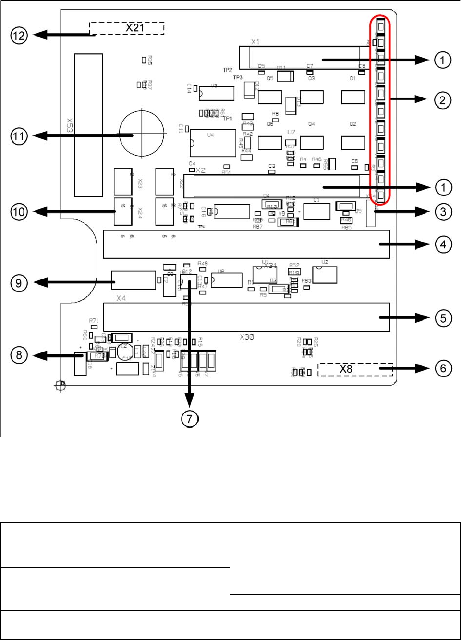
9.4.1.4 P&P Head Main Board
P&P head main board [00352833-xx]
Legend
The main board is mounted directly on the P&P head. This board is connected to the head adapter or
the base adapter via two flat ribbon cables.
1 2 connectors for the 16 bit CAN Bus processor
(not used)
7 EEPROM stores the head specific data (head
exchange, reference run)
2 LEDs (see below) 8 Power supply 15 V for the Track signals D-
Axis (at the moment deactivated via the
jumper X54)
3 X54 Jumper currently set to ON with the new
force measurement board set to OFF (see
LED V2/V_SP)
9 X4 Connector track signals Z axis
4 Connector to the head adapter flat ribbon
cable
10 Connector pneumatic valve (retract unit)