00194614-08 Trainingsdoku. SG X-Serie_X4i SW70x (AL2)_EN.pdf - 第393页
Modular Conveyor Conveyor Settings Setting the Fixed Conveyor Edge (from SW701) 393 Student Guide SIPLACE X-Serie and X4I SW70x (AL2) X series example Setting th e "fixed con veyor edge" in SIPLAC E X, HF serie…
Modular Conveyor
Setting the Fixed Conveyor Edge (from SW701) Conveyor Settings
Student Guide SIPLACE X-Serie and X4I SW70x (AL2) 392
Setting t he Fixed Convey or Edge
Setting the Fixed Conveyor Edge
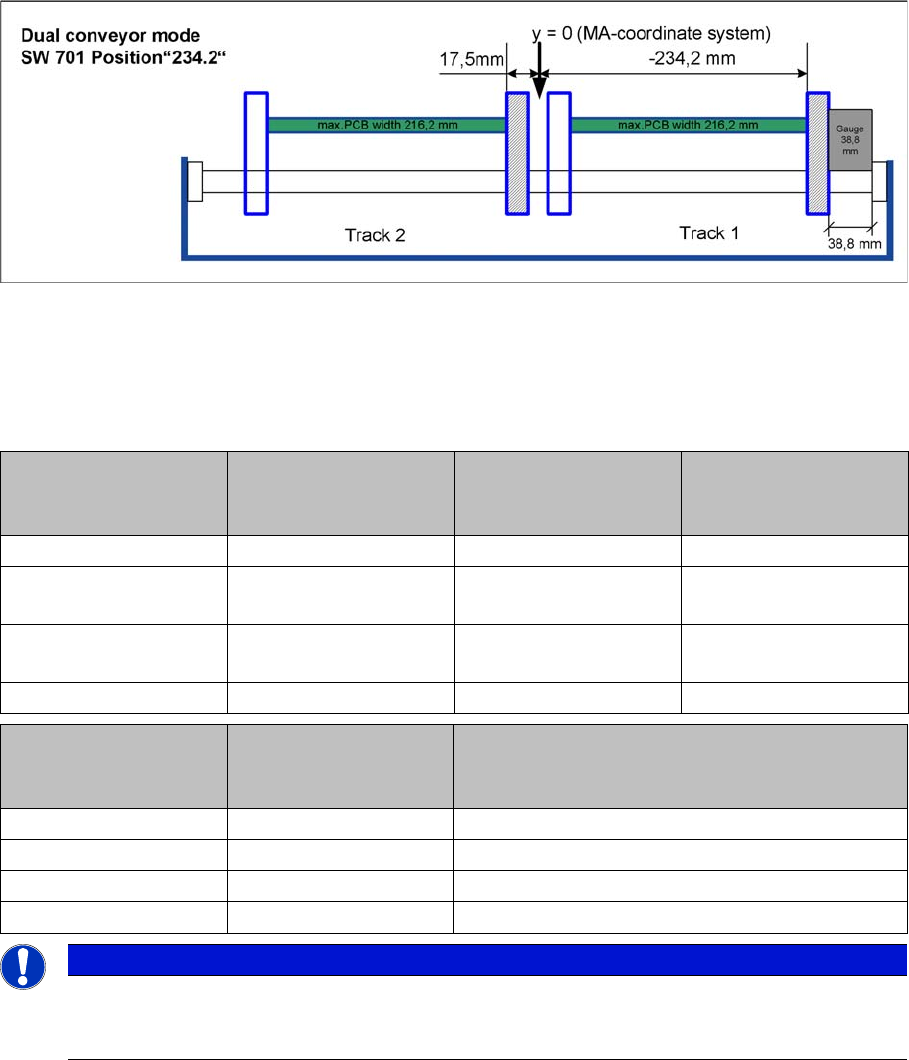
The fixed conveyor edge is always set in the standard mode with right side fixed. You need to set a value
of 38.8 mm between the conveyor base and the fixed conveyor edge, with the help of a gauge.
▪ [03054247-xx] Gauge for fixed conveyor edge DT/ET HS60/D4
▪ [03054248-xx] Gauge for conveyor edge distance DT HS-60/D4
Teach the fixed side with the software and store the value.
Setting the fixed conveyor edge
Values
Measurement is performed between the side flange and the conveyor edge assembly flange.(See also
"X series example")
Machine Single conveyor
Standard width
508 (460) mm
Dual conveyor
Standard width
250 (216) mm
Quad lane
Standard width
114 mm
HF series 19 (43) mm 4.5 (38.8) mm
X series / D3
Until July 2007
19 (43) mm 4.5 (38.8) mm
X series / D3
From July 2007
16 (40) mm 4.5 (38.8) mm 2 mm
X4I 16 (40) mm 4.5 (38.8) mm 2 mm
Machine Single conveyor
Standard width
(460) mm
Dual conveyor
Standard width
(216) mm
HS-60 34,5 mm 30,5 mm
S27 HM 34,5 mm 30,5 mm
D4 34,5 mm 30,5 mm
D1/D2 34,5 mm 30,5 mm
NOTICE
The fixed conveyor side should be adjusted only with the SITEST software and the width
adjustment devices. This ensures that the conveyor edges are in their correct positions
(parallel) i.e. that the conveyor runs straight.
Modular Conveyor
Conveyor Settings Setting the Fixed Conveyor Edge (from SW701)
393 Student Guide SIPLACE X-Serie and X4I SW70x (AL2)
X series example
Setting the "fixed conveyor edge" in SIPLACE X, HF series
Shaft mount (bearing flange)
Legend
▪ After teaching the fixed conveyor edge, you need to recalibrate the PCB reference corner, to prevent
fiducial errors during placement.
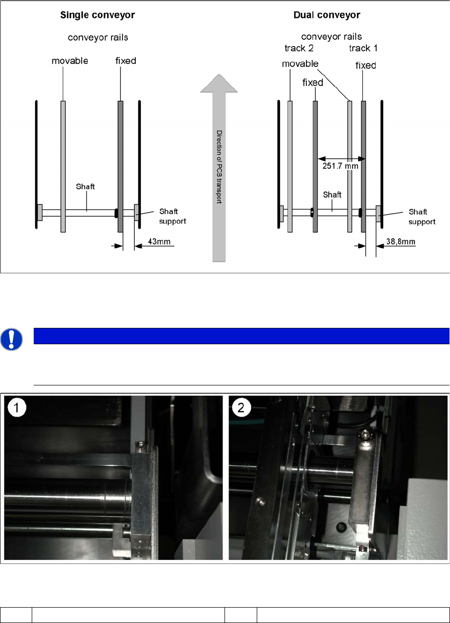
NOTICE
Since July 2007 there is a new version of the shaft mount (bearing flange) for X machines with
single conveyors with 15 mm width instead of 12 mm. The setting for the standard single
conveyor therefore changes to 40 mm when this new version is used.
(1) Bearing flange – first version 12 mm (1) Bearing flange – new version 15 mm
Modular Conveyor
Setting the Fixed Conveyor Edge (from SW701) Conveyor Settings
Student Guide SIPLACE X-Serie and X4I SW70x (AL2) 394
Connecting the Dual Conveyor Lifting Tables
11.3.2.2 Connecting the Dual Conveyor Lifting Tables
► Remove the lifting table plate on conveyor lane 2 in PA1 and on lane 1 in PA2.
► Loosen the lockscrew(s) (4) and use a screwdriver to push the hexagonal circlip over the shaft on
lifting table 1.
► Perform lifting table connection for all placement areas (arrangement rotated by 180°.)
► Configure the new conveyor mode in SIPLACE Pro
NOTICE
The fixed conveyor side may only be adjusted per software and with the width adjustment
devices. This ensures that the conveyor edges are in their correct positions (parallel) i.e. that
the conveyor runs straight.
NOTICE
This option is only a mechanical necessity when you use the dual conveyor as a single
conveyor. The two lifting tables move parallel when they are connected.
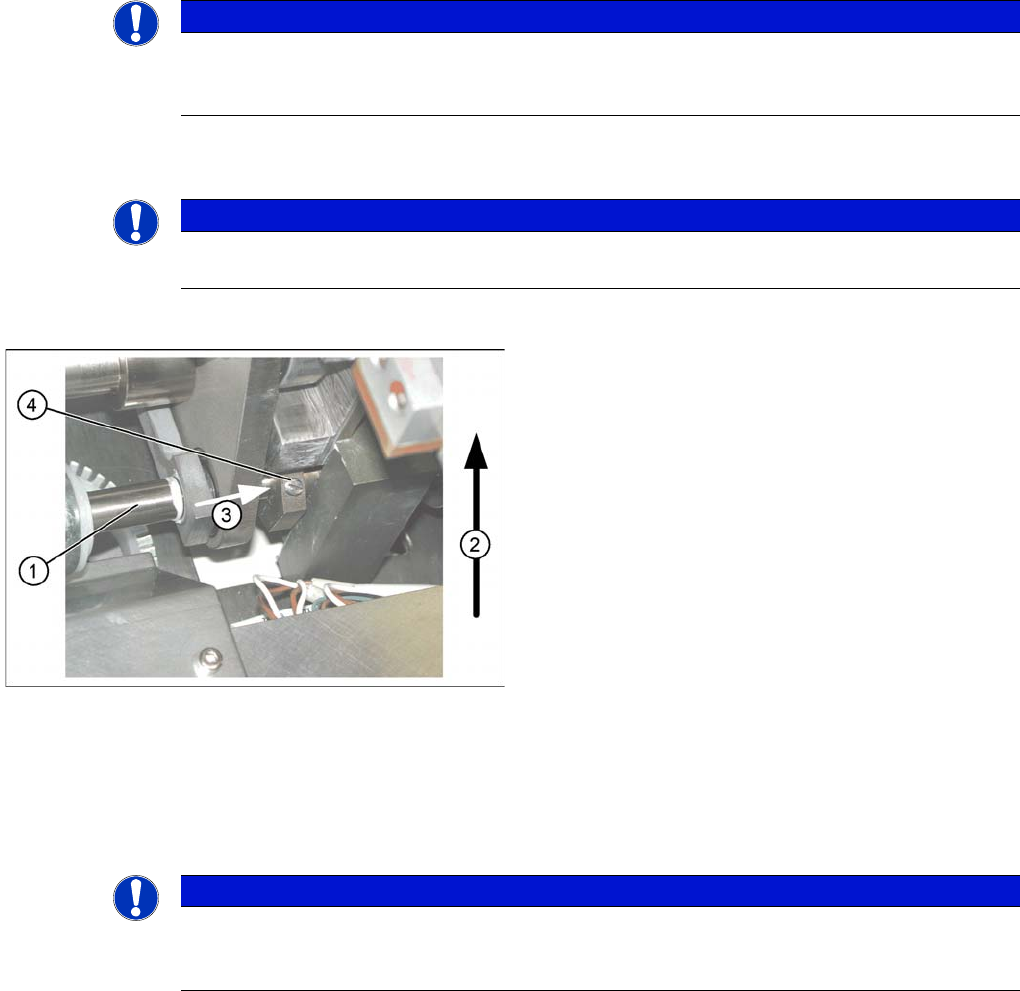
Lifting table
▪ The drive shaft (1) is connected to the piston rod of
the pneumatic cylinder. This shaft couple the second
lifting table of the dual conveyor. The lifting table drive
shaft also has an additional rod with a hexagonal
circlip. They secure the sleeve shaft in the desired
position.
▪ Direction of transport (2).
▪ Direction (3) in which the hollow shaft from lifting
table 2 (1 in PA 2) is to be moved to lifting table 1 (2
in PA 2).
▪ Lock screws (4).
NOTICE
When converting the dual conveyor to a single conveyor (flexible dual conveyor), connect and
disconnect the lifting tables when requested to do so by the station software. This function is
supported by SIPLACE Pro .