00194614-08 Trainingsdoku. SG X-Serie_X4i SW70x (AL2)_EN.pdf - 第336页
TwinHead Description of Boards on the TwinHe ad Settings Student Guide SIPLACE X-Serie and X4I SW70x (AL2) 336 to 5) DIP switch Mechanical Ad justment of th e Z Axis Incre mental Encode r 9.4.1.6 Mechanical Adjustment of…
TwinHead
Settings Description of Boards on the TwinHead
335 Student Guide SIPLACE X-Serie and X4I SW70x (AL2)
To (2) LEDs (description sequence downwards):
Vision Control Board for IC Camera or FC Ca mera
9.4.1.5 Vision Control Board for IC Camera or FC Camera
The vision control board is installed in sector 2 and sector 4 for the stationary cameras.
5 Connector to the head adapter flat ribbon
cable
11 Hole for pneumatic pipe to the vacuum
generator
6 X8: Flex-Cable (Signals: Track signals D-
Axis, Power supply Z Axis/D-Axis, Z
Temperature and, SPI Bus)
12 X21 Connector for vacuum generator
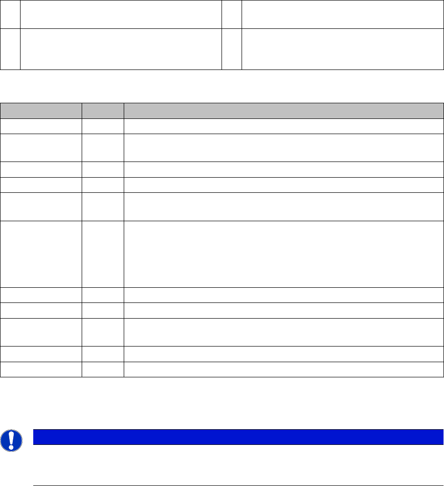
LED Color Description
D8 Green Off – retract unit is moved out – LED shines briefly
D7 KLEMM Green On - display showing that the return cylinder has been projected
downwards.
D6 BERO Green Off - without function (previously: proximity switch Z axis up)
D1 DRUCK Yellow Off - without function (Z pressure)
D2 KLEMM Yellow On – clamping Z axis
Off – retract unit is at top position
V2/V_SP Green Shows the voltage supply 15 V for the D-axis track signals.
Off – at jumper setting ON and old force measurement board.
On – TwinHeads with new force measurement board have the 15V
regulated on the main board i.e. the jumper must be set to OFF and the
LED will be on.
V3 15V_ Green On – 15 V for the D-axis track signals
V1 TEMP Green On - Z axis motor temperature is OK
D14 ALARM Red Off – alarm output for vacuum generator
On – vacuum generator defect
D9 DRUCK Green Off - without function (Z pressure)
D10 24V+ Green On – 24 V for vacuum generator is OK
NOTICE
When using stationary camera ≧ version 04, the Vision control board is integrated into the
cameras. The Vision control board no longer applies in the sectors as well as on newer X
machines and SX machines.
TwinHead
Description of Boards on the TwinHead Settings
Student Guide SIPLACE X-Serie and X4I SW70x (AL2) 336
to 5) DIP switch
Mechanical Ad justment of th e Z Axis Incre mental Encode r
9.4.1.6 Mechanical Adjustment of the Z Axis Incremental Encoder
Vision DC/DC Converter
9.4.1.7 Vision DC/DC Converter
The function of the Vision DC/DC converter is to provide the 42V voltage supply for the stationary
cameras.
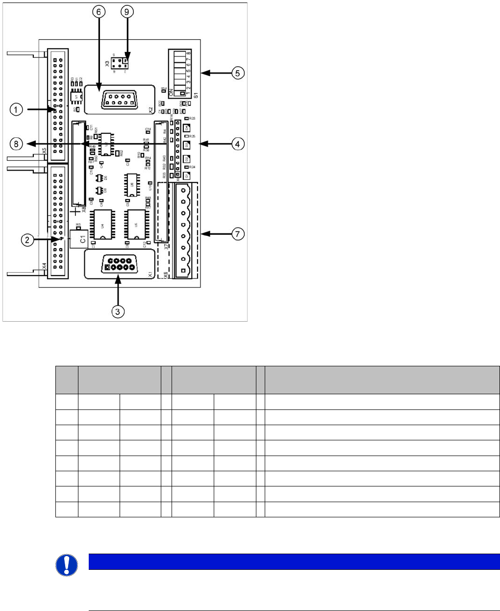
Vision control board TwinHead IC camera
Legend
1. Connector for FC Camera illumination
2. Connector for IC Camera illumination
3. Service connector
4. LEDs (downwards D4 - D1)
+5 V/-15 V/+15 V/+40 V
5. DIP switch
6. Connector CAN Bus
7. Voltage supply for Vision control
Connector for DC/DC converter (sector 2)
DC/DC distributor (sector 4)
8. Connectors for 16 bit CAN Bus processor (TQM
modules)
9. Flash signal (not used for Siplace Vision)
S Sector 2
Main distributor
Sector 4
Subdistributor
Description
1 OFF OFF CAN terminating resistor - 120 Ohm not set
2 OFF OFF Reset
3 OFF OFF Bootstrap
4 OFF OFF TEST
5 OFF ON P1 address switch, gantry ID 1
6 ON ON P0 address switch, gantry ID 2
7 OFF OFF CAN - ID 1
8 OFF OFF CAN -ID 0
NOTICE
The incremental encoder on the Z axis must be adjusted to a distance of 0.4 mm to the
incremental scale. Please adjust the incremental encoder parallel to the incremental scale.
After fitting, check the Z axis track signals (see Section Component Handling).
TwinHead
Settings Parameter and Calibrations
337 Student Guide SIPLACE X-Serie and X4I SW70x (AL2)
The 42V are use for the illumination of the stationary cameras.
When replacing the Vision DC/DC converter, observe the following settings, which depend on your
installation location (main/subdistributor).
Parameter and Calibrations
9.4.2 Parameter and Calibrations
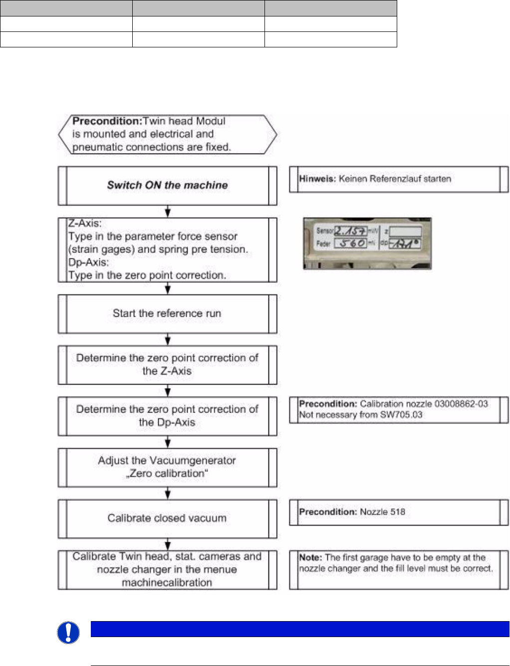
Overview of C alibration Step s and Paramete rs
9.4.2.1 Overview of Calibration Steps and Parameters
Overview of calibration steps and parameters
Main distributor Subdistributor
Bypass 1 (wire jumper) 10 - 13 6 - 13
Bypass 2 (wire jumper) 11 - 12 4 - 12
NOTICE
These steps are necessary during the first initial setup or a replacement of the TwinHead
module. The detailed description can be found on the following pages.