00194614-08 Trainingsdoku. SG X-Serie_X4i SW70x (AL2)_EN.pdf - 第151页
Energy and Compressed Air Supply Overview 151 Student Guide SIPLACE X-Serie and X4I SW70x (AL2) Energy and Compresse d Air Suppl y 5 Energy and Compressed Air Supply Overview 5.1 Overview The diagram be low sh ows wh ere…

Communication and Control
CAN Commands for Reading and Writing the Board IDs Room for Your Sketches and Notes
Student Guide SIPLACE X-Serie and X4I SW70x (AL2) 150
Energy and Compressed Air Supply
Overview
151 Student Guide SIPLACE X-Serie and X4I SW70x (AL2)
Energy and Compressed Air Supply
5 Energy and Compressed Air Supply
Overview
5.1 Overview
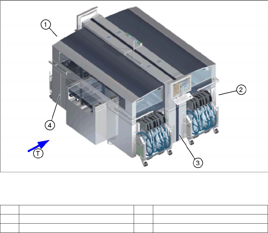
The diagram below shows where the energy supplying and distributing components for system operation
are installed:
Main components
Legend:
1 Power supply 3 Pneumatic Unit
2 Sector distributor for sector 2 4 Sector distributor for sector 4
T Transport direction
Energy and Compressed Air Supply
Naming Convention of Connectors and Cables Power supply
Student Guide SIPLACE X-Serie and X4I SW70x (AL2) 152
Power supply
5.2 Power supply
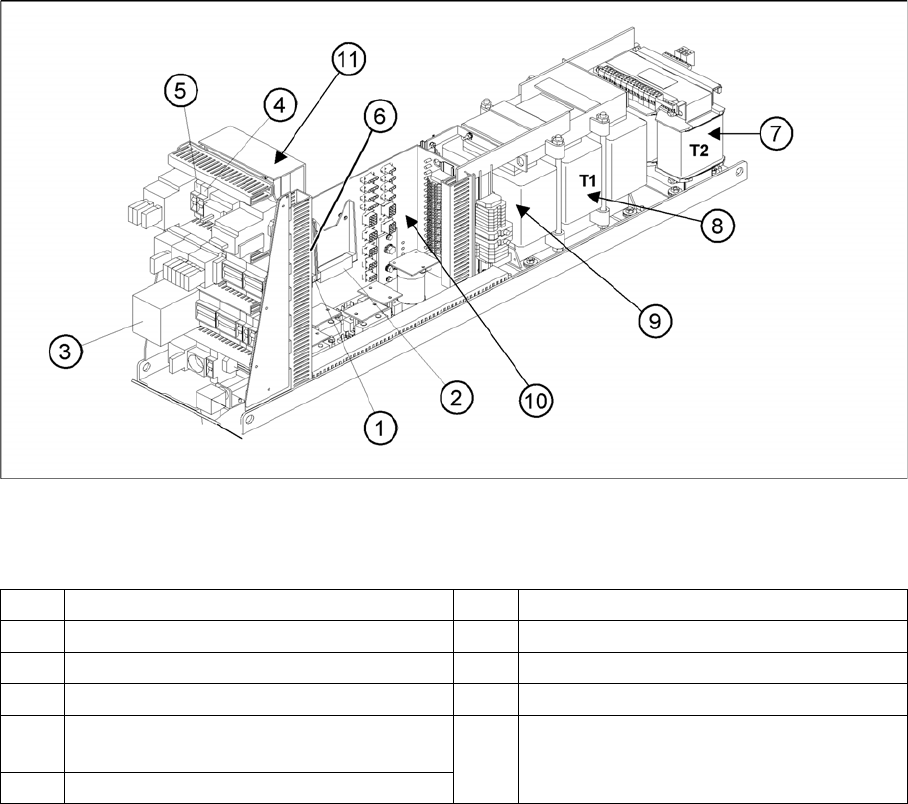
Main power supply unit
Legend
Naming Convention of Connectors and Cables
5.2.1 Naming Convention of Connectors and Cables
The wiring on the SIPLACE X is highly structured. Every cable, connection or distributor uses an exact
term, which refers to the sections and units in question:
Sector 2: term q+
▪ Main-distributor section 2: Designation X1qa, X2qa, X3qa, ...
▪ CAN I/O module (A1): Designation X1qb, X2qb, X3qb, ...
▪ Vision DC/DC converter (A3): Designation X1qc, X2qc, X3qc, ...
▪ Vision control module (A4): Designation X1qd, X2qd, X3qd, ...
▪ Circuit board 8-fold AND operation (A5): Designation X1qe, X2qe and X3qe
Sector 4: term r+
▪ Sub-distributor section 4: Designation X1ra, X2ra, X3ra, ...
▪ CAN I/O module (A1): Designation X1rb, X2rb, X3rb, ...
▪ Vision DC/DC converter (A3): Designation X1rc, X2rc, X3rc, ...
▪ Vision control module (A4): Designation X1rd, X2rd, X3rd, ...
▪ Circuit board 8-fold AND operation (A5): Designation X1re, X2re and X3re
1 DC/DC Converter 24 V 7 Transformer T2
2 DC/DC Converter 5 V and additional 24V 8 Transformer T1
3 Protective contactor combination K6 (SSK) 9 Fuse F61 – Fuse F142
4 Fuse F5 (10A) for star axis 10 Main distributor voltage supply
5 Fuse F11(1A) for transformer inrush
current limitation board
11 Inrush current limitation board
a: Transformer: EST
b: Servo: Ess
6 Discharge inductor L20