00194614-08 Trainingsdoku. SG X-Serie_X4i SW70x (AL2)_EN.pdf - 第451页
MTC2 Construction and mode of operation Installation MTC 2 451 Student Guide SIPLACE X-Serie and X4I SW70x (AL2) Each axis first moves to its ph ysic al home positio n then che cks the position of the t wo software limit…
MTC2
Incorporating the MTC in the SIPLACE station Construction and mode of operation
Student Guide SIPLACE X-Serie and X4I SW70x (AL2) 450
Incorpor ating the MTC in the SIP LACE stat ion
13.2.2 Incorporating the MTC in the SIPLACE station
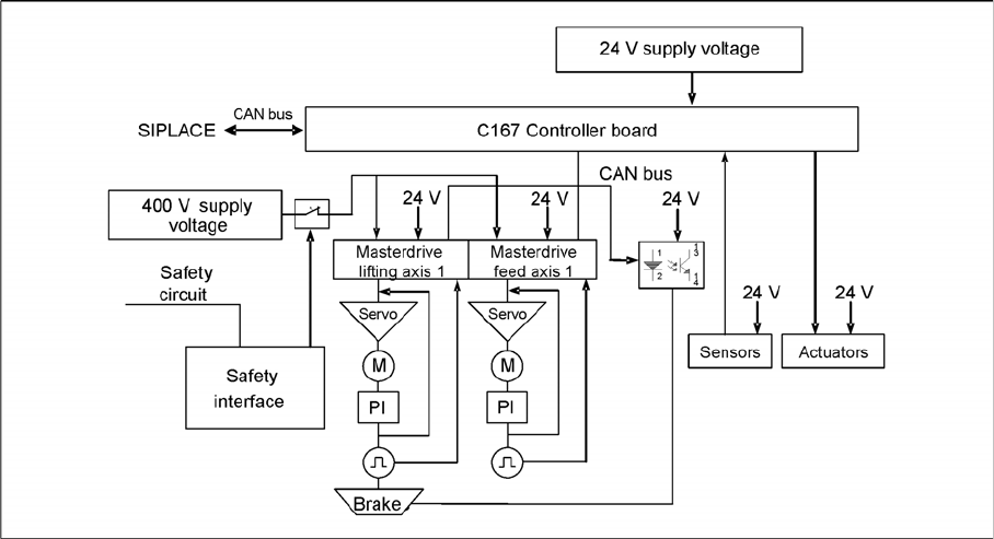
MTC2 interfaces and power supply (shown for tower 1)
CAN Bus
This interface is used for all commands which are sent by the machine controller of the SIPLACE station.
Example: Reference position run and transfer of set-up data.
400 V power supply
The MTC2 is supplied externally with 400 V (USA/Japan: 208/204 V).
EMERGENCY STOP interface
The MTC2 is incorporated into the safety circuit of the SIPLACE station. This provides feedback in the
form of a protective circuit voltage of 24 V. This protective circuit voltage switches the relevant
combination circuit breaker and thus the 400 V of the inverters for the Masterdrives.
The contactors switch off the servo voltage (400 V) and also immediately switch off the power supply to
the brake.
The signaling contact (make contact) of the EMERGENCY STOP button is connected to the input of the
SIPLACE safety signalling system. The break contact interrupts the 24 V protective circuit voltage of the
SIPLACE machine.
If the EMERGENCY STOP circuit in a machine is interrupted (EMERGENCY STOP button), the master
drives of the MTC2 will trip. Both systems are then not under power.
When one of the two MTC2 protective doors is opened, only the control voltage of the relevant tower
falls.
Reference position run
13.2.3 Reference position run
When the MTC2 is switched on, a reference position run needs to be performed for the servo axes, as
for the SIPLACE station. If the MTC2 remains switched on when the SIPLACE station is switched off and
back on, it will report that it has already been referenced.
During the reference position run, both towers move into their reference positions simultaneously. The
two feed axes are moved first and then the two lifting axes.

MTC2
Construction and mode of operation Installation MTC 2
451 Student Guide SIPLACE X-Serie and X4I SW70x (AL2)
Each axis first moves to its physical home position then checks the position of the two software limit
switches and finally stops in the software zero position (this corresponds to the relevant zero offset of
the physical home position). The positions adopted by the axes are then defined as reference and
calibration positions.
The reference run for an individual axis is performed as follows:
▪ The current zero offset is sent to the Masterdrive.
▪ The controller queries the "neutral position" of the light barrier and waits for a rising edge.
▪ If the axis is already positioned in the light barrier, it issues a "HIGH" signal. The axis moves in a
positive direction until the light barrier delivers a falling edge. The axis then moves in the negative
direction again.
▪ If the axis is not positioned in the light barrier, it issues a "LOW" signal. The axis moves in a negative
direction.
▪ The axis moves in the negative direction until the light barrier delivers the necessary rising edge and
the first rotor zero position (index) has been found.
▪ This procedure is necessary, since the zero pulses of the resolver angular encoder are repeated with
each revolution and thus appear several times within the possible travel range.
▪ The axes move to both software limit switches in the maximum and minimum positions to within a
few millimeters, to check the saved data.
▪ Finally, they move to the current zero offset.
When the axes have moved to all four reference positions, the SIPLACE station searches for the two
fiducials on the feed axes. The position which is found is used later to define the pick-up position of
components. The fiducials must be available in the MVS file of the line computer.
Installati on MTC 2
13.2.4 Installation MTC 2
The MTC2 can only be run in conjunction with a SIPLACE station and not as an independent machine.
The settings (machine data) are saved in the battery backed memory of the machine controller and are
only valid for this particular machine.
When the MTC2 has been delivered, the following steps must be performed before the machine is used
for the first time:
► Check the basic height and if necessary set it (see the User Manual).
► Check that the power supply has been set correctly (see Chapter 13.3.14 or Adjustment Instruction).
► Check that all axes can move freely.
► Check the toothed belt for correct tension and damage: See settings guide
► If there is evidence of damage to the toothed belt, it must be replaced (see the Service Instructions).
► Prepare the SIPLACE station (see Chapter 13.2.6).
► Dock the MTC2 onto the SIPLACE station (see the User Manual).
► Switch on the SIPLACE station and the MTC2.
► Log on to the station computer software at the Service access level.
► Start SITEST.
► In the basic view, switch to the menu for the MTC2 .
► Perform a reference run on the MTC2 .
► Perform a reference run on the SIPLACE station.
CAUTION
If the axes are not moved completely to the software limit switches and an error message
appears on the screen for the motor controllers (master drive), one of the axes must be
calibrated again.
MTC2
Modules of the controller Construction and mode of operation
Student Guide SIPLACE X-Serie and X4I SW70x (AL2) 452
► Perform a functional test on the safety equipment by carrying out each of the following actions
individually during subsequent reference runs:
► Press the EMERGENCY STOP button.
► Open the protective doors.
► Leave the tower locking mechanism open before the reference run.
There must be an EMERGENCY STOP and a corresponding error message must be output on the
screen.
► Undo the relevant action and confirm the error message.
Modules of the controller
13.2.5 Modules of the controller
C167 con troller board
13.2.5.1 C167 controller board
The controller program (firmware) on the C167 controller board is saved in a flash EPROM. The version
number can be queried from the SITEST program.
The machine data and the set-up are saved in RAM. After the machine is switched off, the data is held
by a buffer battery (buffer time approx. 3.5 years), which is also located on the C167 controller board. In
addition, an electrolytic capacitor ("Goldcap") with a capacity of 1 F is fitted. This saves the data for
approximately 8 hours when the backup battery is changed.
The "neutral position" light barriers and the software limit switches are wired to the Masterdrives and are
made available there via the CAN bus of the controller.
Tasks:
▪ Communicating with the station computer of the SIPLACE station
▪ Controlling the machine via the firmware
▪ Exchanging data with the axis controllers
▪ Saving the firmware (flash EPROM)
▪ Saving the machine data and the set-up (battery-buffered RAM)
▪ Saving machine-specific parameters, such as serial numbers (in the EEPROM)
▪ Providing a realtime clock
▪ Inputs for sensors
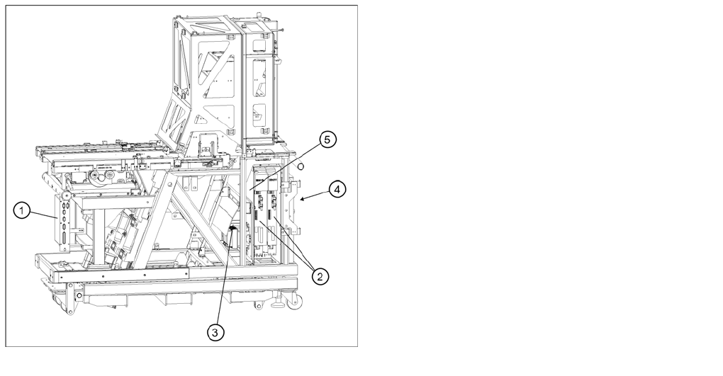
Modules of the controller
Legend
1. C167 controller board
2. Masterdrives (shown for tower 1)
3. 24V power supply (behind the combination circuit
breakers)
4. Electronics board
5. Mounting plate