00194614-08 Trainingsdoku. SG X-Serie_X4i SW70x (AL2)_EN.pdf - 第103页
Communication and Control CAN Bus Communication DP Drives, C&P20A and CPP Head 103 Student Guide SIPLACE X-Serie and X4I SW70x (AL2) Time sequence from up to down fo r image acquisition communica ti on Communicatio n…
Communication and Control
Communication SIPLACE Vision CAN Bus
Student Guide SIPLACE X-Serie and X4I SW70x (AL2) 102
Communication SIPLAC E Vision
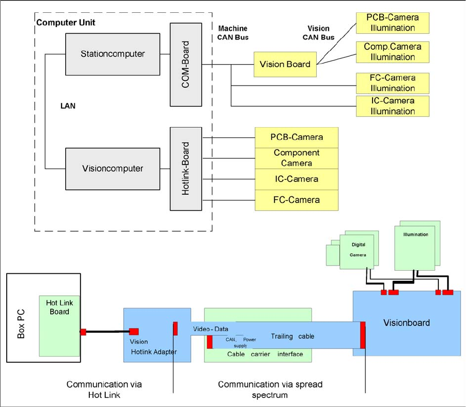
4.3.6 Communication SIPLACE Vision
Overview SIPLACE Vision
The communication between the computers is via LAN cables. The station computer sends the
commands for image acquisition to the Vision computer and receives the measurement result. The
station computer also sends the illumination values for the respective component shapes. The images
recorded are transferred digitally via the Vision board to the hotlink adapter, using the spread spectrum
and are then sent via the hotlink connection to the Vision computer, for evaluation. The result is sent to
the station computer.
Communication During Image Acquisition
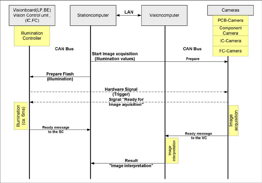
4.3.6.1 Communication During Image Acquisition
The main communication between the Vision system and station computer is the transmission of
illumination values. These values, stored in the CS, are sent via CAN bus to the camera in question. As
soon as the camera should take the picture, the camera illumination is activated by a trigger. From this
moment on the row of LEDs which provides the different illumination levels shines according to the
illumination value. This illumination value can have 0 = dark up to 255 = bright. All illumination levels start
lighting at the same moment. The value 0-255 determines the length of the illumination time.
The maximum length of illumination is limited to 6 ms.
Communication and Control
CAN Bus Communication DP Drives, C&P20A and CPP Head
103 Student Guide SIPLACE X-Serie and X4I SW70x (AL2)
Time sequence from up to down for image acquisition communication
Communication DP Drives, C&P20A and CPP Head
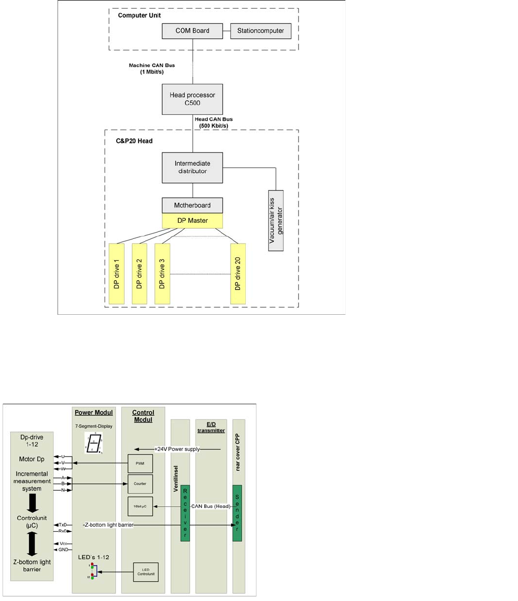
4.3.7 Communication DP Drives, C&P20A and CPP Head
The TQM module on the head interface C500 communicates via the CAN Bus (1M/Bit/s) with the station
computer.
The communication to the C&P20A or CPP head is via an additional CAN Bus, which sends the data
with 500 KBit/s.
The DP axes are controlled via the DP master (SCS). 4 actions are performed by the machine control at
the same time:
▪ Starts a certain rotary axis after pickup/placement (pickup angle/placement angle)
▪ Starts a certain rotary axis after Vision (correction angle)
▪ Waits for a certain rotary axis before Vision (positioning command not allowed)
▪ Waits for a certain rotary axis before pickup/placement (positioning command not allowed)
Communication and Control
Communication CPP Head CAN Bus
Student Guide SIPLACE X-Serie and X4I SW70x (AL2) 104
CAN Bus-controlled head functions on the C&P20A head
Communication CPP Head
4.3.8 Communication CPP Head
Communicati on to the DP Dri ves
4.3.8.1 Communication to the DP Drives
The DP drives are controlled via a common hardware
component, the SCS (Single Core Solution). This
consists of two boards, the power and the control
modules, with a microprocessor for the sequence control.
The control data is sent from the head processor and is
then transmitted via the head CAN bus.
The communication with the light barrier Z down is via a
separate interface, directly to the power module. This is
necessary as a light barrier Z down is integrated into each
segment.