00194614-08 Trainingsdoku. SG X-Serie_X4i SW70x (AL2)_EN.pdf - 第352页
Component Handling Changeover Table with One Hand O peration - Function Changeover T able Student Guide SIPLACE X-Serie and X4I SW70x (AL2) 352 Fitting th e Docking Un it 10.1.3.5 Fitting the Docking Unit To guarantee th…
Component Handling
Changeover Table Changeover Table with One Hand Operation - Function
351 Student Guide SIPLACE X-Serie and X4I SW70x (AL2)
Position ing the D ocking Unit in t he Machine
10.1.3.4 Positioning the Docking Unit in the Machine
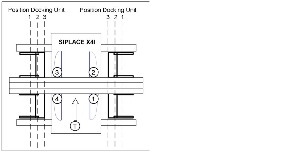
Positioning the docking unit
SIPLACE X4I
1. Gantry 1
2. Gantry 2
3. Gantry 3
4. Gantry 4
T = transport direction
The docking units can be installed at three different
positions in the machine for each location. The position of
the docking unit depends on the machine type and the
head configuration. Gantries 2 and 4 have been rotated
in the SIPLACE X4I machine. This means that the
docking units at all four locations are mounted in position
3. This creates short travel ranges between the feeders
and the board.
Component Handling
Changeover Table with One Hand Operation - Function Changeover Table
Student Guide SIPLACE X-Serie and X4I SW70x (AL2) 352
Fitting the Docking Unit
10.1.3.5 Fitting the Docking Unit
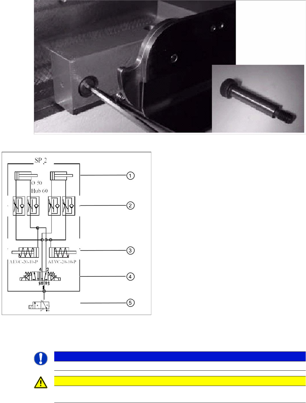
To guarantee the precise fit of the table feed device for accurate pickup of small components, the
docking unit on the inside of the machine is fixed with a special fitting screw. When fitting the docking
unit for the changeover table, make sure that this screw is fixed first, before the other screws.
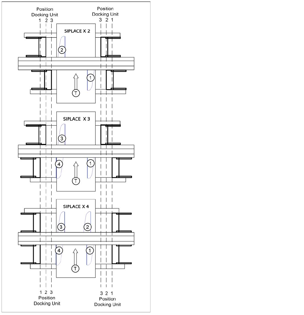
SIPLACE X2, X3 and X4
1. = Gantry 1
2. Gantry 2
3. Gantry 3
4. Gantry 4
T = transport direction
The docking unit of the MTC2 is always installed in
position 3 (see diagram).
Component Handling
Changeover Table Setting the COT Height
353 Student Guide SIPLACE X-Serie and X4I SW70x (AL2)
Special fitting screw on the changeover table docking unit
Setting the COT Height
10.1.4 Setting the COT Height
The changeover table can be adjusted to any height between 830 and 950 mm by removing the two pins
from the hollow shafts, which hold the table plate.
Pneumatic diagram docking unit
Legend
1. Pneumatic cylinder for moving the cam disks. This
means that the changeover table plate will move
43mm horizontally and 20 mm vertically into the
machine.
2. Throttle valves for adjusting the speed of the
pneumatic cylinders (time adjustment). Adjustment is
made without the changeover table and should take
approx. 2 seconds for docking and undocking.
3. Pneumatic cylinders for ejecting the COT during the
undocking procedure.
4. 5/2 way valve for controlling the pneumatic cylinder.
5. Safety valve in case of electrical faults
NOTICE
Adjustment of the COT height is in general identical for S and X tables.
CAUTION
Always use the screwed eyelet to fix the table plate, irrespective of whether you want to raise
or lower the component trolley.