00194614-08 Trainingsdoku. SG X-Serie_X4i SW70x (AL2)_EN.pdf - 第265页
Collect, Pick and Place Head (CPP) Important Information Application 265 Student Guide SIPLACE X-Serie and X4I SW70x (AL2) Collect, Pick and Place He ad (CPP) 8 Collect, Pick and Place Head (CPP) Importan t Inform ation …

C&P20A
Pneumatic Plan for Nozzle Changer Room for Your Sketches and Notes
Student Guide SIPLACE X-Serie and X4I SW70x (AL2) 264
Collect, Pick and Place Head (CPP)
Important Information Application
265 Student Guide SIPLACE X-Serie and X4I SW70x (AL2)
Collect, Pick and Place He ad (CPP)
8 Collect, Pick and Place Head (CPP)
Importan t Inform ation
8.1 Important Information
Overview
8.2 Overview
Applicat ion
8.2.1 Application
The CPP head can be used in the following machines:
▪ X series (X2, X3, X4, X4I)
▪ SX1 - machine with one gantry
▪ SX2 - machine with two gantries
▪ SX4 - machine with four gantries
CAUTION
Head exchange X series
When replacing the TwinHead with a CPP head with MTC2 in this placement area, you need
to fit a bumper extension, to limit the Y travel range. After switching the machine back on, you
then need to redetermine the machine zero point and the travel ranges.
When you use a TwinHead again, you need to remove the bumper extension.
CAUTION
Risk of head crash!
When installing a CPP head with a stationary camera, this needs to be fitted in the top position
otherwise there is a risk of a head crash!
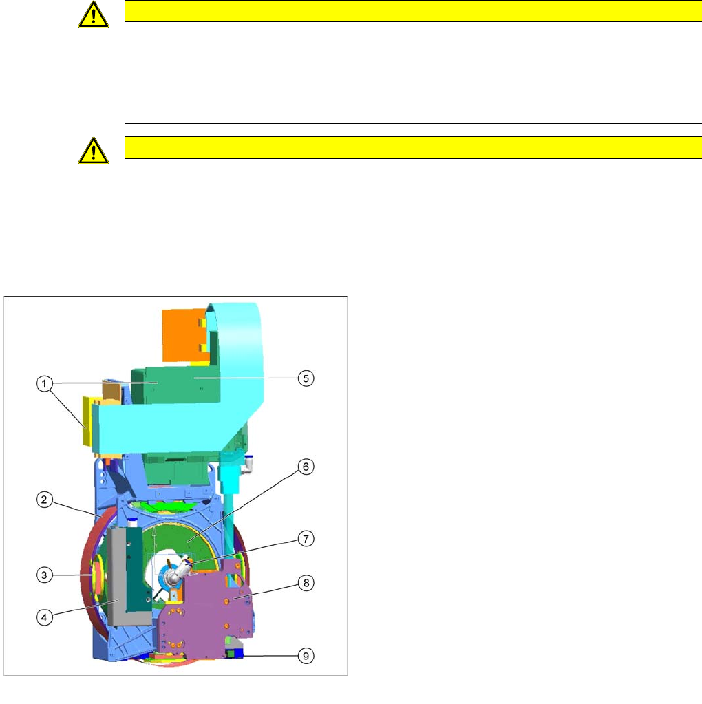
Overview of CPP head
CPP placement head without camera SST29
[03070108-xx]
CPP placement head with camera SST29 [03053528-xx]
Legend
1. Intermediate distributor 1 and 2
2. Star motor (integrated into the head housing)
3. DP axis (as direct drive)
4. Pressure control valve
5. Component camera (behind the intermediate
distributor, standard: SST29)
6. Single core solution (SCS) – DP drive control
7. Holding circuit supply, integrated venturi nozzles and
valve assembly (valve terminal)
8. Z axis with return cylinder
9. Component sensor in the pick and place position

Collect, Pick and Place Head (CPP)
Configuration Overview
Student Guide SIPLACE X-Serie and X4I SW70x (AL2) 266
Configura tion
8.2.2 Configuration
The CPP head with 12 segments can be configured as follows:
▪ Low installation height (CPP_L)
▪ High installation height (CPP_H)
Requirem ents
8.2.3 Requirements
The following requirements need to be met for using the CPP head in X series machines:
▪ A364 axis controller with servo amplifier SDS120-1.5Z2 or HCU (Head Control Unit)
▪ Station software ≥ SW702
▪Box PC
▪ Head plate for CPP head
▪ X tables and X feeders
▪ Addressing the nozzle changer via the CAN node module or the FCU (Feeder Control Unit)
Technical Data
8.2.4 Technical Data
The component spectrum depends on the component camera fitted and the resulting placement mode.
Special Features of CPP Head
8.2.5 Special Features of CPP Head
▪ There are various placement modes: C&P mode, P&P mode and mixed mode.
▪ Symmetrical head design: The head can be fitted on the left or right.
Component spectrum Component camera
SST29
Component camera
SST38
IC camera SST33
C&P mode (min.
component)
0201 01005 (0603)
C&P mode (max.
component)
27x27 mm / (µBGA to
18x18 mm)
16x16 mm
P&P mode (max.
component)
50x40 mm
Mixed mode (max.
component)
32x32 mm
Component height (CPP_H) max. 8.5 mm C&P mode
max. 8.5-11.5 mm in P&P and mixed mode
Component height (CPP_L) max. 6 mm, at max. placement performance
Placement accuracy +/- 50 µm (4 sigma) in C&P mode with SST38
+/- 55 µm (4 sigma) in C&P mode with SST29
+/- 45 µm (4 sigma) in P&P mode with stationary cameras
Placement force 1 N +/- 0.6N current sensor
2.2N +/- 0.5N current sensor
2.6N +/- 0.8N light barrier mode
3.0N-6.0N +/- 1N current sensor
6.0N - 10.0N +/-1.5N current sensor
Weight of head approx. 5.3 kg with component camera
Component weight: max. 4 g in C&P mode, mixed mode
max. 8 g in P&P mode
Component cameras SST29 (0201 to 27x27, Standard)
SST38 (01005 to 16x16)