00194614-08 Trainingsdoku. SG X-Serie_X4i SW70x (AL2)_EN.pdf - 第427页
Head Modularity Compressed Air Distributor for the Placement H eads Twin Head 427 Student Guide SIPLACE X-Serie and X4I SW70x (AL2) Pneumatic distributor for trailing cable CFK02/04
Head Modularity
Twin Head Compressed Air Distributor for the Placement Heads
Student Guide SIPLACE X-Serie and X4I SW70x (AL2) 426
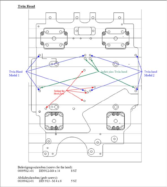
Twin Head
12.7.3 Twin Head
Compress ed Air Distribut or for the Placement Heads
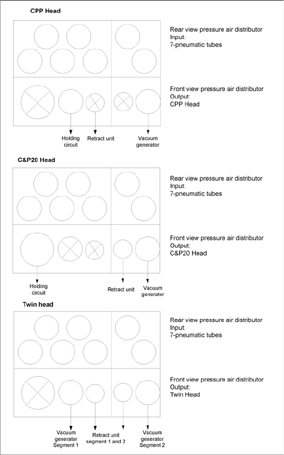
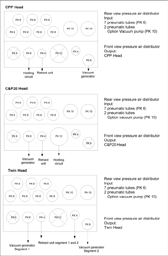
12.8 Compressed Air Distributor for the Placement Heads
There are two different pneumatic distributors which are fixed under the head interface.
The distributor used depends on the trailing cable version in use. This means that the old pneumatic
distributor is used for the old trailing cable on the gantries CFK 02 and 04 and the compressed air
distributor version 02 is used for gantry CFK 06 with the vacuum pump option.
The compressed air for the pressure control valve and the return cylinder is made available via a supply
line from the compressed air distributor for those placement heads which are prepared for Fast Head
Exchange.
Head Modularity
Compressed Air Distributor for the Placement Heads Twin Head
427 Student Guide SIPLACE X-Serie and X4I SW70x (AL2)
Pneumatic distributor for trailing cable CFK02/04
Head Modularity
Twin Head Slots in the Axis Unit
Student Guide SIPLACE X-Serie and X4I SW70x (AL2) 428
Pneumatic distributor for trailing cable CFK06/
Slots in the Axis Unit
12.9 Slots in the Axis Unit
Further development of the X series, to include the SW603 and the A364 axis controller board, provides
operators with new head configuration options and axis assignment options on the axis controller board.
General description of the servo and axis controller board assignment
In X series machines, we differentiate between the X2 machine with one axis unit in PA2 and the X3 or
X4 machines with two axis units, one each in PA1 and PA2. In addition, we also have the different head
configurations at the gantries and their assignment of servo and axis boards in the axis units.
Axis controller board assignment:
The following applies for both axis unit 1 and 2:
1. Max. 3 axis boards per axis unit (slot 1-3).
2. Axis board in slot 1 always for the lower value gantry in the placement area
Assignment (from top to bottom) X, Y, star, Z) for TH (X, Y, Z_segment 2, Z_segment 1)
3. Axis board in slot 2 always for the higher value gantry in the placement area
Assignment (from top to bottom) X, Y, star, Z) for TH (X, Y, Z_segment 2, Z_segment 1)
4. The axis controller board in slot 3 for C&P20A is not used.