00194614-08 Trainingsdoku. SG X-Serie_X4i SW70x (AL2)_EN.pdf - 第497页
MTC2 Masterdrives Set ting the CAN bus address at the master drive PMU 497 Student Guide SIPLACE X-Serie and X4I SW70x (AL2) These brief instructions show how to ente r the addr ess for t he Masterdrive of th e lifting a…
MTC2
Factory settings Masterdrives
Student Guide SIPLACE X-Serie and X4I SW70x (AL2) 496
▪ r004 = Output current inverter, converter
▪ r006 = Actual DC intermediate circuit voltage
▪ r009 = Temperature motor
▪ r069 = Software version
Index 1 Masterdrives
Index 2 Option BG Slot A
Index 3 Option BG Slot B
Index 4 Option BG Slot C
▪ U003 = Parameter set version:
For the feed axis of tower 1/2 software version
For the lifting axis of tower 1/2 software version
▪ U501 = Machine data
▪ P060 = Function parameters for selection of current menu
Index 4: Address
▪ P095 = Motor list with standard motors
▪ P096 =Function parameter motor
Define serial Interface:
▪ P700 interface address of COM 1
▪ P701 baud rate 8 is equal to 38400
Factor y setting s
13.4.3 Factory settings
Reset the Master drives to the define defaults
You must change 3 Parameters to define the defaults
after this you can download the parameter set for the axis.
▪ Change parameter P053 from 7 to 6 (this value is a binary code 0111 --> 0110).
▪ Set Parameter P060 from 7 to 2.
▪ Change Parameter P970 from 1 to 0. Parameter-Reset is started.
Check the serial interface and CAN Bus address after RESET:
▪ Adjust the V24 (RS232) Interface.
– Parameter P700 = 0
– Parameter P701 --> index 1 = 8 (= baud rate 38400).
▪ Check the address for Can -Bus Parameter P918.
▪ Download the Parameter set for the Axis with the Laptop.
Setting t he CAN bus addre ss at the maste r drive P MU
13.4.4 Setting the CAN bus address at the master drive PMU
It is necessary to enter the addresses of the feed and lifting axes on the PMU’s (Parameterization Units)
for the Master drives on initial commissioning of the MTC and after the replacement of the Master drives.
This can be performed external to the MTC. The Master drives must be supplied with 24 V DC. The
control for the related axis must be shut down.
NOTICE
The MTC2 parameter sets differ from one another, due to the mechanical construction.
CAUTION
When setting factory defaults, the axis concerned must not be subject to position control.
MTC2
Masterdrives Setting the CAN bus address at the master drive PMU
497 Student Guide SIPLACE X-Serie and X4I SW70x (AL2)
These brief instructions show how to enter the address for the Masterdrive of the lifting axis for tower 1.
For more detailed information, see the chapter "Parameterization" in the user manual for "SIMOVERT
MASTERDRIVES".
The following addresses are provided for the lifting and feed axes:
► Select , to go to the parameter numbers.
► Step with , until you reach the seven segment number P060 . This is the menu selection.
► Select . A number will appear on the display. This is the Parameter menu.
► Step with , until you reach the number 4 . ("4" means "module configuration").
► Select . You will see 004 on the display. This is the status indicator for Module
configuration.
► Select , to go to the parameter numbers. You will see P060.
► Step with , until you reach the seven segment number P918 . This is the parameter number for
the bus address.
► Select , to go to the parameter index. You will see 001 , which is index 1. (an index is always
indicated by a small line).
► Select , to go to the parameter value. You will see 1 . This is the address of the lifting axis for
tower 1.
NOTICE
For setting the CAN Bus address you could use the software "Drive Monitor". For manual
adjustment of the CAN bus address, see "13.3 MTC2 Calibration and Settings" [ ➙ 464].
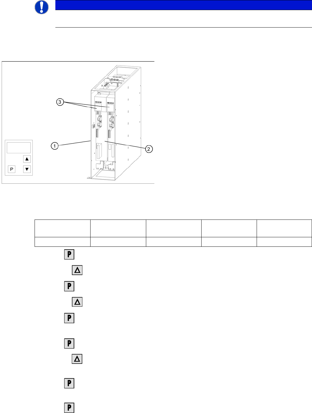
Masterdrives of the lifting and feed axes (shown here for
tower 1)
Legend:
1. Masterdrive of the lifting axis for tower 1
2. Masterdrive of the feed axis for tower 1
3. Masterdrive of the lifting axis for tower 2
4. Masterdrive of the feed axis for tower 2
5. Control panels
Lifting axis 1
(PMU 1)
Feed axis 1
(PMU 2)
Lifting axis 2
(PMU 3)
Feed axis 2
(PMU 4)
Address 1 2 3 4
MTC2
Downloading Parameter Sets Masterdrives
Student Guide SIPLACE X-Serie and X4I SW70x (AL2) 498
► Select , to return to the parameter numbers. You will see P918.
► Step with , until you reach the number P060 . Now you are back in the menu selection.
► Select and set with 1 . You will be taken back to the Parameter menu .
► Select . You will see 009.
► Select . You will see P60.
► Set r000 .
► Select . The initial state will be restored.
Downloading Parameter Sets
13.4.5 Downloading Parameter Sets
Requirem ents
13.4.5.1 Requirements
▪ CD ROM Drive Monitor
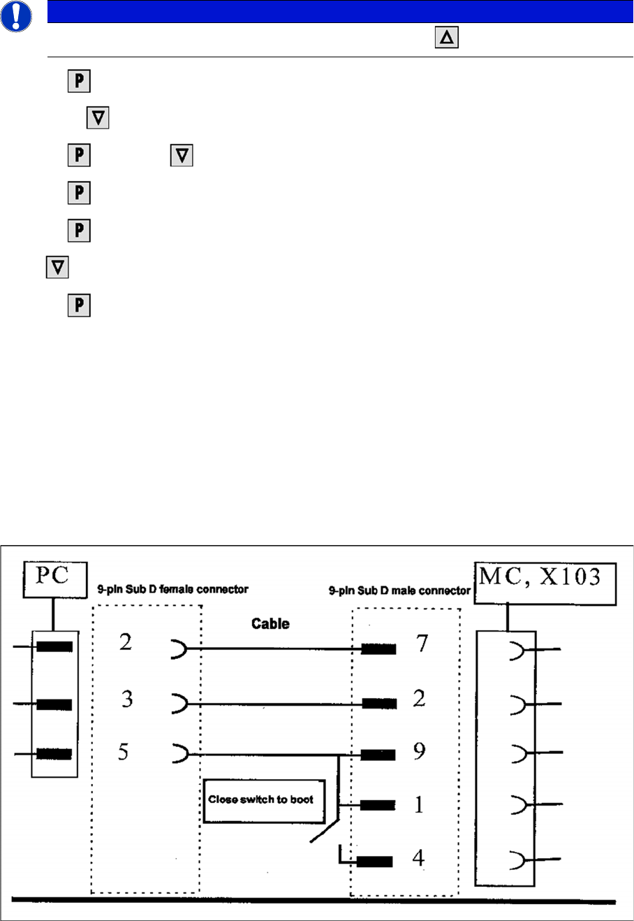
▪ Cables for laptop and master drives (03021720-01)
▪ Parameter set for lifting axis Tower 1 and Tower 2
▪ Parameter set for feed axis Tower 1 and Tower 2
▪ Simovert Masterdrive for the Lifting axis (00354979-01)
▪ Simovert Masterdrive for the Feed axis (00354980-01)
Cable configuration for the connection between the laptop and the master drive
NOTICE
For the PMU 2 (feed axis 1) setting, you will need to step with until you reach 2 .