00194614-08 Trainingsdoku. SG X-Serie_X4i SW70x (AL2)_EN.pdf - 第234页
C&P20A Measuring Z Axis Position for Component R ecognition by the Comp onent Sensor Pickup and Placement Cycle for C&P20A Student Guide SIPLACE X-Serie and X4I SW70x (AL2) 234 Measuring Z Axis Position for Comp …
C&P20A
Reference Run for C&P20A Head Determining the Vacuum and Threshold Values
233 Student Guide SIPLACE X-Serie and X4I SW70x (AL2)
Determining the Vacuum and Threshold Values
7.3.7 Determining the Vacuum and Threshold Values
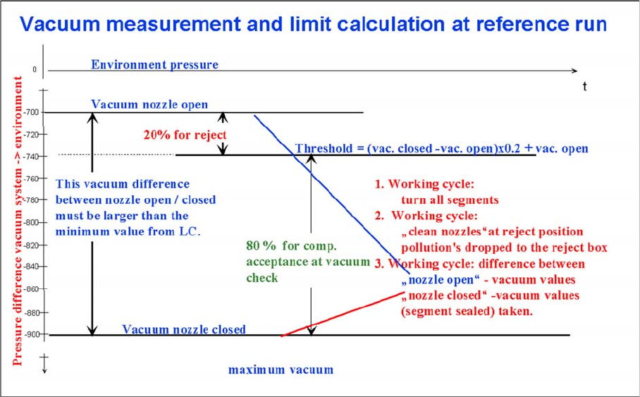
Measuring and calculating the vacuum values for a reference run
▪ The vacuum is measured twice at the reference point: first with open and then with closed nozzle
tips.
▪ The value with closed segment does no longer depend on the ambient pressure it is controlled by
the pressure control valve. The nozzle fit (nozzle pickup error) and the quality (contamination/
damage) of the nozzle tip influence the vacuum measurement values.
▪ The value by open pressure control valve depends on the nozzle size and condition. The smaller the
nozzle, the greater the open valve value will be. This nozzle-specific value is preset by the SIPLACE
Pro computer. A contaminated or blocked nozzle will also give a higher valve.
▪ The difference between the open and closed nozzles has been preset by the programming system
as an ideal case minimum value. This value is different for all nozzle types e.g. 120 mbar for 1004,
1014 nozzles. If these values are not achieved, the error message “Vacuum difference open-closed
is too low” will appear.
▪ The threshold for component acceptance is also set now. Assumed are following values for a 1004
nozzle: a value of 660 mbar when the nozzle is open and a value of 852 mbar when the nozzle is
closed. The calculation is performed as follows:
Vacuum distance = (852 (closed) - 660 (open))= 192 mbar
This is greater than the vacuum distance required in the parameter specifications for this nozzle type
(120 mbar). The open vacuum of 660 mbar is significantly greater than the required 250 mbar.
C&P20A
Measuring Z Axis Position for Component Recognition by the Component Sensor Pickup and Placement Cycle for C&P20A
Student Guide SIPLACE X-Serie and X4I SW70x (AL2) 234
Measuring Z Axis Position for Comp onent Rec ognition by the C omponent Sensor
7.3.8 Measuring Z Axis Position for Component Recognition by the Component Sensor
While the Z axis moves downwards, the nozzle interrupts the laser beam of the component sensor. The
axis position is saved and later used for the calculation of the component height and component
presence. At the upwards movement of the Z axis, the laser beam is no longer interrupted and the axis
position is saved again. The component presence can be determined during placement by the
programmed component height (SIPLACE Pro) and the nozzle length, calculated during the height
reference run by the Z axis position counter.
Pickup and P lacement Cycle for C&P20A
7.4 Pickup and Placement Cycle for C&P20A
Working Position on Placement Head
7.4.1 Working Position on Placement Head
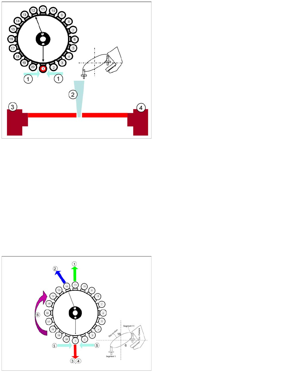
Nozzle length measurement at reference run for
component recognition
Legend
1. Component sensor
2. Nozzle
3. Receiver
4. Transmitter
During the height reference run, the component sensor
measures the Z axis position for each segment, to detect
the presence/absence of components in the pickup and
placement position. During placement the Component
Sensor can also recognize dirty nozzles.
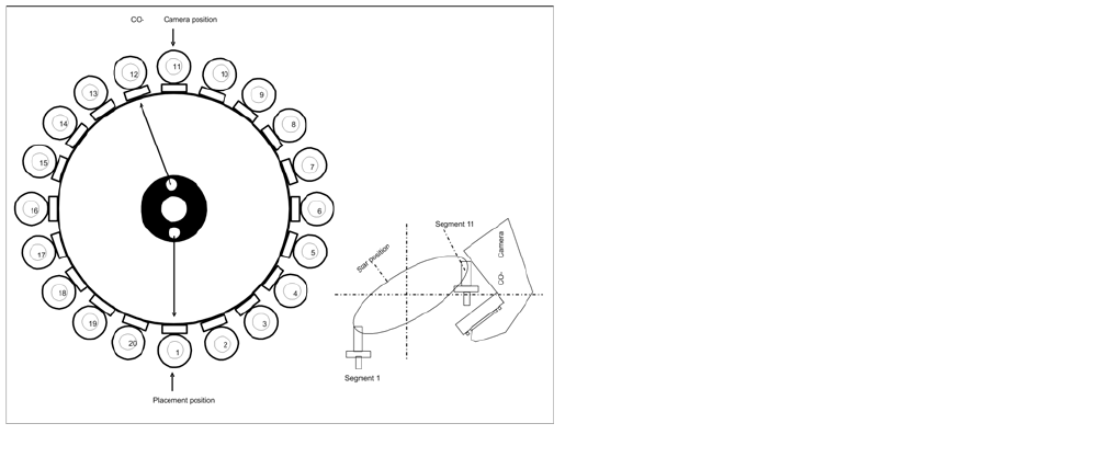
Working Position on Placement Head
Legend
1. Optical centering (component camera)
2. Vacuum measurement holding circuit
3. Vacuum measurement placement circuit
4. Pickup/placement station and reject position
5. Position of component sensor
6. Working direction
C&P20A
Pickup and Placement Cycle for C&P20A C&P20A in Home Position 0°
235 Student Guide SIPLACE X-Serie and X4I SW70x (AL2)
C&P20A i n Home Position 0°
7.4.2 C&P20A in Home Position 0°
Board P osition Re cognition
7.4.3 Board Position Recognition
We differentiate between standard position recognition and dual position recognition.
PCB – position recognition (standard position recognition)
Board position recognition is used to determine the exact position of the board in the machine (conveyor
--> placement area).
PCB position recognition is performed with gantry 4 for placement area 1 and with gantry 2 in placement
area 2.
There should be at least two fiducials on each PCB. These are then used to calculate the X/Y position
and the rotary angle of the board, in the conveyor system.
The fiducials should not be on the same line.
Up to 3 fiducials can be programmed for position recognition. With this third fiducial you can also
determine and correct any displacement within the board (shrinkage, stretched).
Dual position recognition (for alternating mode only)
Dual position recognition is required in order to guarantee the placement accuracy. Materials change
according to the temperature they are subjected to and the same applies to the machine gantries.
Dual position recognition is performed with gantry 1 in placement area 1 and with gantry 3 in placement
area 2.
In the case of dual position recognition, gantry 1/3 uses the fiducial position recognition values from
gantry 2/4 to calculate the placement offset for gantry 1/3. Depending on the arrangement of fiducials on
the board, either 2 or 3 fiducials will be used for dual position recognition.
The fiducials for dual position recognition are selected so that the calculation performed can be as
accurate as possible.
Temperature compensation
A further measure to ensure placement accuracy is the temperature compensation with the help of
sensors on the head plate. The head plate features two temperature sensors, the temperature values of
which are regularly checked via a separate bus system.
The software uses these temperature values to calculate an offset value, which is added to the head
offset.
▪ Head offset SW 60x is the distance PCB <--> component camera
C&P20A in Home Position 0°
Star position
▪ Digits: 10
▪ Angle: 0°
1° is equivalent to 1000 digits
The Z axis retract unit prevents segment 1 from falling.