00194614-08 Trainingsdoku. SG X-Serie_X4i SW70x (AL2)_EN.pdf - 第301页
Collect, Pick and Place Head (CPP) Pickup and Placement Cycle for CPP S tandard Mode - Placement: Z Axis Down 301 Student Guide SIPLACE X-Serie and X4I SW70x (AL2) Standard Mode - Placement: Z Axis D own 8.4.13 Standard …
Collect, Pick and Place Head (CPP)
Detailed Standard Pickup Procedure: Z Axis Down Pickup and Placement Cycle for CPP
Student Guide SIPLACE X-Serie and X4I SW70x (AL2) 300
Detailed Standard Pickup Procedure: Z Axis Down
8.4.11 Detailed Standard Pickup Procedure: Z Axis Down
▪ Enables vacuum query: segment open threshold ? Yes
Component sensor switches due to Z axis movement:
▪ Measurement value for nozzle length "empty"
Axis controller:
▪ Enable "light barrier down" signal.
LB down switches:
▪ End signal Z axis positioning down
▪ Z axis measurement value for pickup height optimization
Detailed Standard Pickup Procedure: Z Axis Up
8.4.12 Detailed Standard Pickup Procedure: Z Axis Up
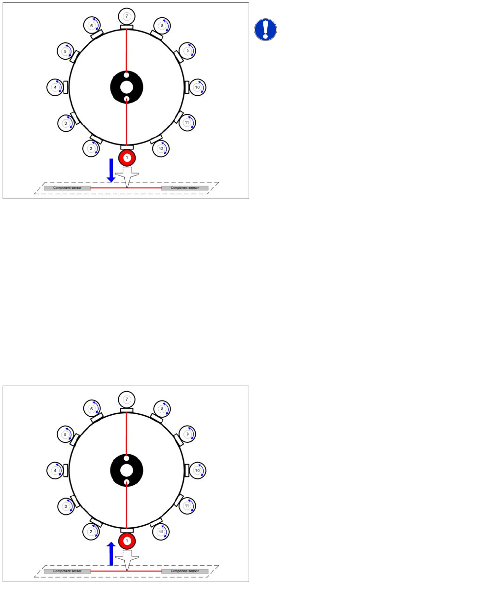
Star position 0°: detailed pickup sequence - Z axis down
Start gantry axes to the pick up position of next feeder.
NOTICE! The vacuum for the holding circuit of
each segment is switched on via the valve terminal, just
before pickup is performed. The vacuum is used for
picking up components and mainly comes from the
pressure control valve. The holding circuit vacuum is only
used to hold the component on the nozzle during the star
rotation.
▪ Start signal for X and Y axes to move to next feeder.
End signal X, Y axes:
▪ X/Y end position signals available.
Z axis starts:
▪ Z axis starts positioning downwards
End position signal for star axis
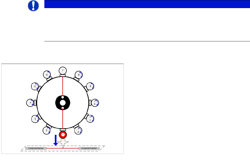
Detailed pickup procedure: Z axis up
LB down switches:
▪ Vacuum Threshold comp. picked reached? Yes
Z axis starts:
▪ Z axis starts positioning upwards
Component sensor switches due to Z axis movement:
▪ Z axis position value; nozzle length + comp.height
measurement threshold reached? Yes
Z axis position in safety area:
▪ reset light barrier state,
▪ X, Y gantry axes start
▪ start component feeder (communication to feeder
table)
Vacuum query:
▪ Vacuum threshold for holding circuit reached? Yes
▪ Star axis starts.
Collect, Pick and Place Head (CPP)
Pickup and Placement Cycle for CPP Standard Mode - Placement: Z Axis Down
301 Student Guide SIPLACE X-Serie and X4I SW70x (AL2)
Standard Mode - Placement: Z Axis D own
8.4.13 Standard Mode - Placement: Z Axis Down
Axis controller:
▪ Enable signal for "light barrier down" function
LB down switches:
▪ End signal Z axis positioning downwards;
▪ Digital pressure control valve: switches "Air blast ON"
▪ Pickup/placement position; air blast threshold "place component" reached? Yes
NOTICE
Since the travel paths for each axis can be calculated and are therefore known, the next action
(e.g. starting the Z axis) is started via position flags. These are sent by the predecessor action
(e.g. star axis). This enables the Z axis to start moving 10 ms earlier (depending on the
definition). It no longer needs to wait for the end position signal from the star axis. The end
position signal is therefore no longer in use.
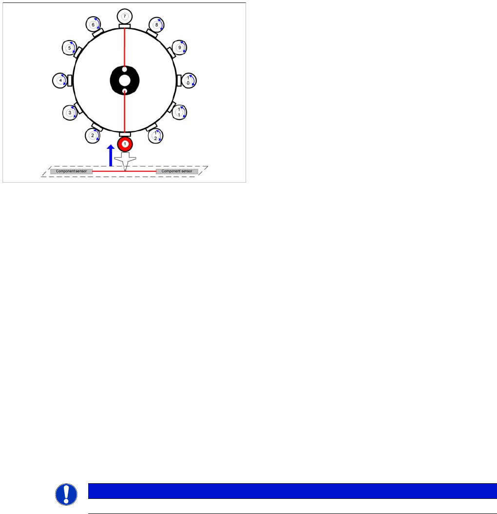
Detailed component placement procedure: Z Axis Down
In this mode (light barrier down) the placement force at
the placement head is around 2N.
End position signal for X and Y axes--> Z axis starts:
▪ Positioning of Z axis downwards
▪ Component sensor checks component. Z axis
measurement value - nozzle length "with component"
- threshold reached? Yes
End position signal for star axis:
▪ Performsing vacuum test "before placement".
"Vacuum closed" threshold reached? YES to
determine whether the component is held by holding
force on the nozzle.
Collect, Pick and Place Head (CPP)
Standard Mode - Placement: Z Axis Up Settings on the CPP Head
Student Guide SIPLACE X-Serie and X4I SW70x (AL2) 302
Standard Mode - Placement: Z Axis U p
8.4.14 Standard Mode - Placement: Z Axis Up
Optical Nozzle Query
8.4.15 Optical Nozzle Query
▪ After the reference run, the gantries move into the wait position and performs the first nozzle
scanning. During the production, a nozzle scanning run is performed after 350 head cycles (can be
set by SIPLACE service if required) and after the completion of the board currently processed. This
ensures that the nozzle quality is continually checked during the production process:
– All nozzles listed in the scan parameters of the station database will be measured by the
component camera.
– If there is any deviation from the defined size, shape or brightness, the machine will show the
message: Nozzle worn down or contaminated.
▪ Tiny nozzles may touch the solder paste or the glue because of component shift and the minimum
component height.
▪ The number of components per segment (number of head cycles), after the next nozzle query has
been performed, should be adjusted to the customer's process requirements. This check is always
performed after completing PCB processing.
Settings on t he CPP Head
8.5 Settings on the CPP Head
Board D escriptio ns
8.5.1 Board Descriptions
See also
7.5.1.1 Head Adapter for C&P20A on X Machines with A364 [ ➙ 248]
8.5.1.1 Base Adapter for CPx on SX4 Machines with HCU [ ➙ 303]
8.5.1.2 Head Interface on SX4 Machines with HCU [ ➙ 304]
Detailed component placement procedure: Z Axis Up
LB down switches:
▪...
▪ Pickup/placement position; air blast threshold "place
component" reached? Yes
▪ Start signal for upwards movement
Z axis starts:
▪ Z axis positioning upwards
Head firmware:
▪ Digital pressure control valve: switches air blast OFF
▪ Reset "light barrier down" signal
Axis controller:
▪ Z axis measurement value for nozzle "empty" and
▪ Z axis in safe area =
▪ Enable X, Y gantry axes.
Vacuum query:
▪ Vacuum threshold for holding circuit reached? Yes
▪ Star axis starts.
NOTICE
The nozzle quality check can be configured in four different levels, via the station interface.