00194614-08 Trainingsdoku. SG X-Serie_X4i SW70x (AL2)_EN.pdf - 第490页
MTC2 Machine Data MTC2 Calibration and Settings Student Guide SIPLACE X-Serie and X4I SW70x (AL2) 490 Voltage distributor termin al X01 13.3.5.3 Voltage distributor terminal X01 Motor Cir cuit Break er 13.3.5.4 Motor Cir…
MTC2
MTC2 Calibration and Settings Converting the power supply
489 Student Guide SIPLACE X-Serie and X4I SW70x (AL2)
Convertin g the power suppl y
13.3.5 Converting the power supply
To operate the MTC2 in the USA or in Japan, the power supply needs to be changed from 400 V, 50 Hz
to 208/204 V, 50/60 Hz.
Tools and Equipment
13.3.5.1 Tools and Equipment
▪ 1 set of screwdrivers
▪ 3 additional bridges
Procedur e
13.3.5.2 Procedure
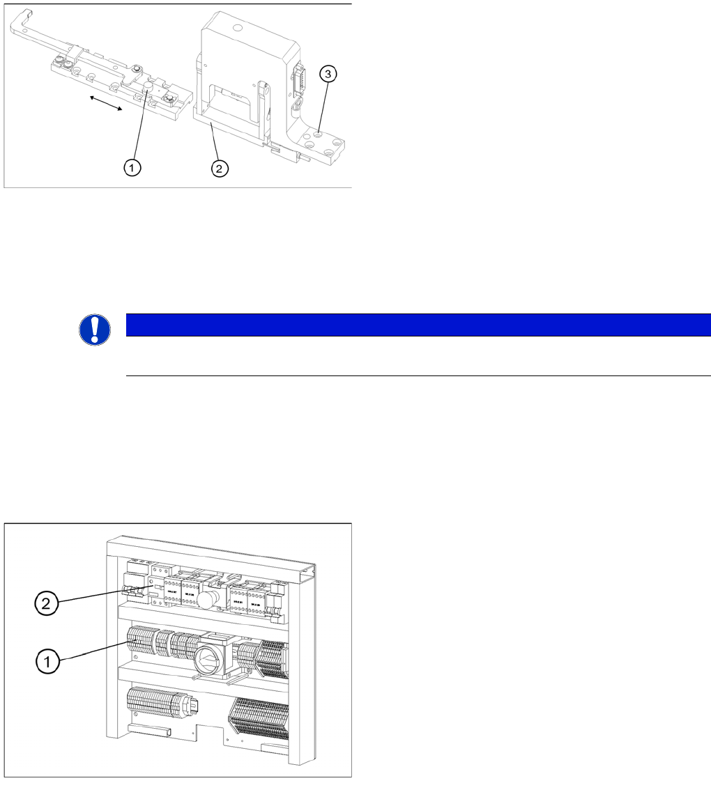
Setting the disengaging mechanism
Legend
1. Driver guide roller in dead center position
2. Disengaging mechanism aperture
3. Disengaging mechanism securing screws
NOTICE
To convert the power supply from 208/204 V to 400 V, the same procedure must be carried out
in the reverse order.
Electronics board
Legend
1. Bridges on the voltage distributor terminal X01
2. Motor Circuit Breaker
MTC2
Machine Data MTC2 Calibration and Settings
Student Guide SIPLACE X-Serie and X4I SW70x (AL2) 490
Voltage distributor termin al X01
13.3.5.3 Voltage distributor terminal X01
Motor Circuit Breaker
13.3.5.4 Motor Circuit Breaker
Machine Data
13.3.6 Machine Data
General machine parameters
13.3.6.1 General machine parameters
Software version: Date 11.2004
Serial number, MTC2: 214
Delta fiducial transfer position: 10000
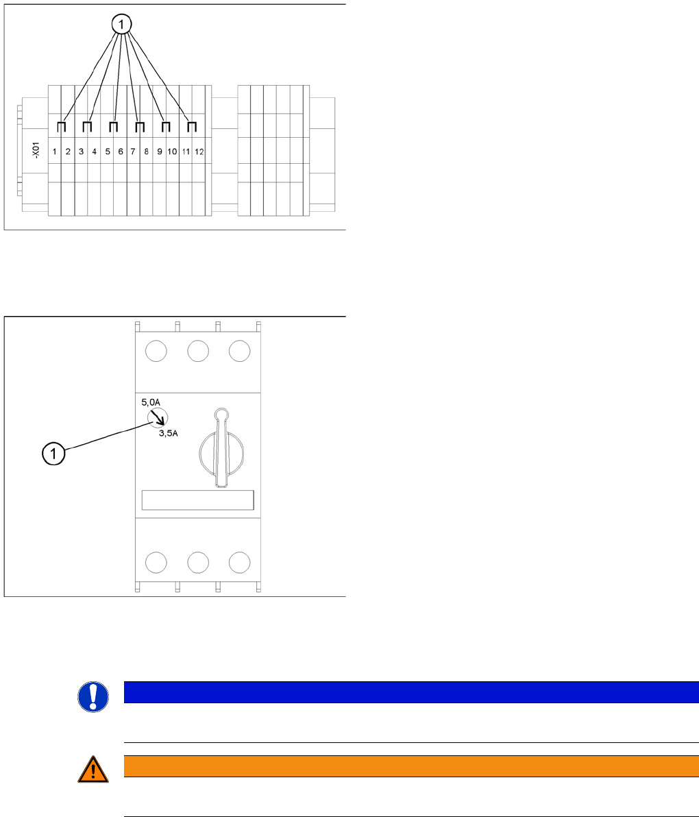
Voltage distributor terminal X01
Legend
1. Bridges on the voltage distributor terminal X01
► Removing the three bridges between 2-3, 6-7 and 10-
11.
► Connect the six bridges between 1-2, 3-4, 5-6, 7-8, 9-
10 and 11-12.
Motor Circuit Breaker
Legend
1. Rotary regulator of the motor protection switch
► It is always 3.5 A.
NOTICE
The machine parameters listed are only an example of a data record. The individual values can
be different for each MTC2 .
WARNING
Incorrectly set machine data can result in a crash between the lifting and feed axes or at the
limit positions of these axes.
MTC2
MTC2 Calibration and Settings Machine Data
491 Student Guide SIPLACE X-Serie and X4I SW70x (AL2)
Machine parameters for t ower 1
13.3.6.2 Machine parameters for tower 1
Machine pa rameters for t he lifting a xis on tower 1
Machine parameters for the lifting axis on tower 1
Positions
▪ Offset, zero position: -500.300 mm
▪ Position of operator removal position, cassette 1: 0 mm
▪ Position of operator removal position, cassette 2: 103.150 mm
▪ Position of operator removal position, cassette 3: 206.250 mm
▪ Position of operator removal position, cassette 4: 309.450 mm
▪ Position of operator removal position, cassette 5: 412.600 mm
▪ Position of WTC removal position, cassette 1: 28.300 mm
▪ Position of WTC removal position, cassette 2: 131.500 mm
▪ Position of WTC removal position, cassette 3: 234.500 mm
▪ Position of WTC removal position, cassette 4: 337.800 mm
▪ Position of WTC removal position, cassette 5: 440.950 mm
▪ Minimum position: -3.233 mm
▪ Maximum position: 573.472 mm
▪ Service position: 165.000 mm
Travel parameters
▪ Default speed, WTC: 50
▪ Default acceleration, WTC: 50
▪ Acceleration, lower threshold value: 1
▪ Acceleration, upper threshold value: 50
▪ Acceleration, axis command: 50
▪ Acceleration, axis command: 50
Machine pa rameters, fee d axis, tower 1
Machine parameters, feed axis, tower 1
Positions
▪ Position of WTC removal position, cassette 1: 0 mm
▪ Position of WTC removal position, cassette 2: -0.180 mm
▪ Position of WTC removal position, cassette 3: -0.220 mm
▪ Position of WTC removal position, cassette 4: 0.230 mm
▪ Position of WTC removal position, cassette 5: -0.320 mm
▪ Offset, zero position: -11.350 mm
▪ Component transfer position: 646.500 mm
▪ Minimum position: -3.389 mm
▪ Maximum position: 652.548 mm
▪ Service position: 249.999 mm
Travel parameters
▪ Default speed, moving WTC out: 150
▪ Default speed, moving WTC in: 150
▪ Default acceleration, WTC: 100