00194614-08 Trainingsdoku. SG X-Serie_X4i SW70x (AL2)_EN.pdf - 第70页
Overview C&P20A Head Overview of Components Student Guide SIPLACE X-Serie and X4I SW70x (AL2) 70 Nozzle Chan ger for C &P20 Head 3.2.9.3 Nozzle Changer for C&P20 Head The nozzle changer consists of at l e a s…
Overview
Overview of Components C&P20A Head
69 Student Guide SIPLACE X-Serie and X4I SW70x (AL2)
Each segment has its own DP drive for rotating the components into the correct position. The segments
are therefore no longer rotated into the correct angle in one single star position but can now be rotated
separately from one another.
Each segment has its own vacuum generator.
The Z drive for the segments is realized via a linear motor with linear position measuring system, which
makes it highly accurate. In the pickup/place position, the Z axis moves the segments up or down
(vertical direction).
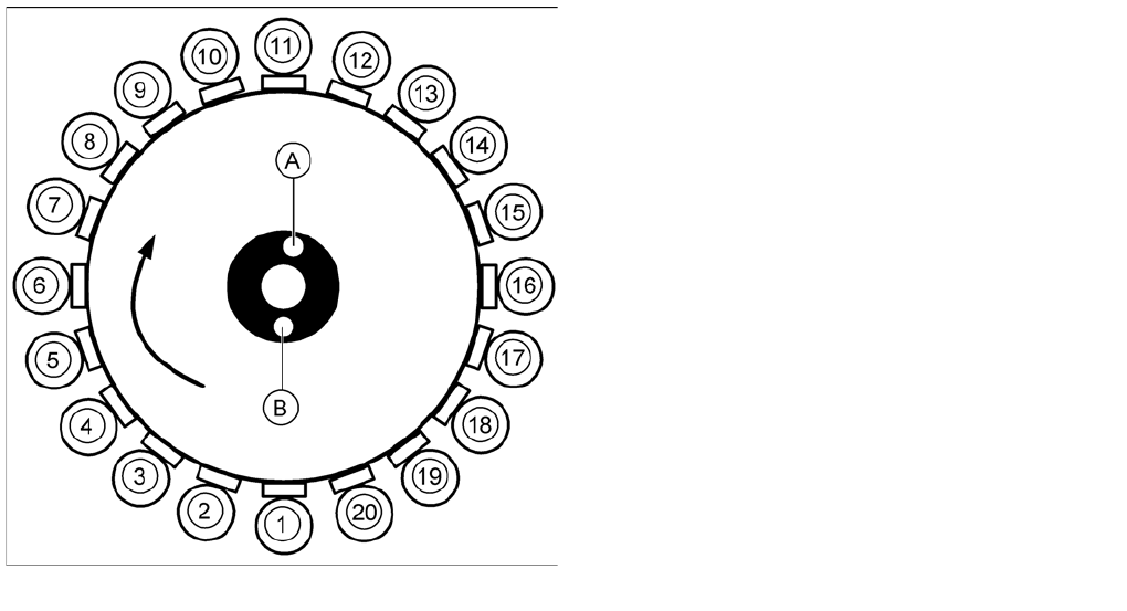
Overview of F unctions for Star Statio ns 1 - 20
3.2.9.2 Overview of Functions for Star Stations 1 - 20
Star station 1:
▪ Component pickup, placement or rejection
▪ Component sensor: Checks whether component is present after pickup and before placement.
▪ Component sensor: Checks whether no component is present after pickup and before placement.
▪ Vacuum/air blast measurement for pickup/placement circuit
Star station 12:
▪ Vacuum measurement for holding circuit
▪ By rotating the star axis, the vacuum value can be measured at each segment.
Star station 11:
▪ Optical measurement of components
Star station 2 - 10 and 12 - 20
▪ In these star stations, the component at the segment can be rotated into the correct position.
▪ In star stations 2 - 10, the component is rotated into the placement position.
▪ In star stations 12 - 20, angular correction is performed after optical measurement.
▪ Rotation to the correct angle position can be performed at any of the star stations, except 1 and 11.
Overview of functions for star stations 1 - 20
Legend
▪ 1 to 20: star stations 1 to 20
▪ A : Vacuum measurement holding circuit
▪ B : Measurement of pickup/place circuit
Overview
C&P20A Head Overview of Components
Student Guide SIPLACE X-Serie and X4I SW70x (AL2) 70
Nozzle Changer for C&P20 Head
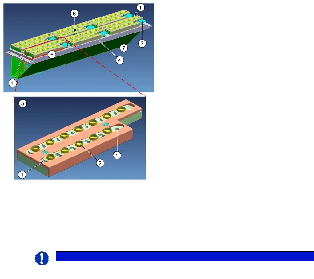
3.2.9.3 Nozzle Changer for C&P20 Head
The nozzle changer consists of at least six and up to twelve magazines, each of which has twelve nozzle
garages. The magazines are seated on a support. Each magazine is fixed with the help of a snap
fastener and can be released with a lever.
Each garage can be configured with different nozzle types.
Head Modularity Note
Head Modularity Note
Nozzle changer and nozzle magazines
Legend
1. Calibration fiducials
2. Nozzle garage
3. Unlocking lever
4. Magazine support
5. Magazines
6. LED green (magazine query)
7. Changeover table side
Between changeover table and 1st row. The nozzle
reject bin is located on the right, next to the 1st row.
Optionally, a nozzle changer can be installed for the
placement heads. This enables the nozzle configuration
to be changed quickly, thus allowing the Collect&Place
head to be quickly adapted to the needs of the placement
process.
NOTICE
The new nozzle changer carriers are identical for the C&P20A and CPP heads. This means that
you only need to change the magazines for head modularity.
Overview
Overview of Components CPP Head
71 Student Guide SIPLACE X-Serie and X4I SW70x (AL2)
CPP Head
3.2.10 CPP Head
Overview
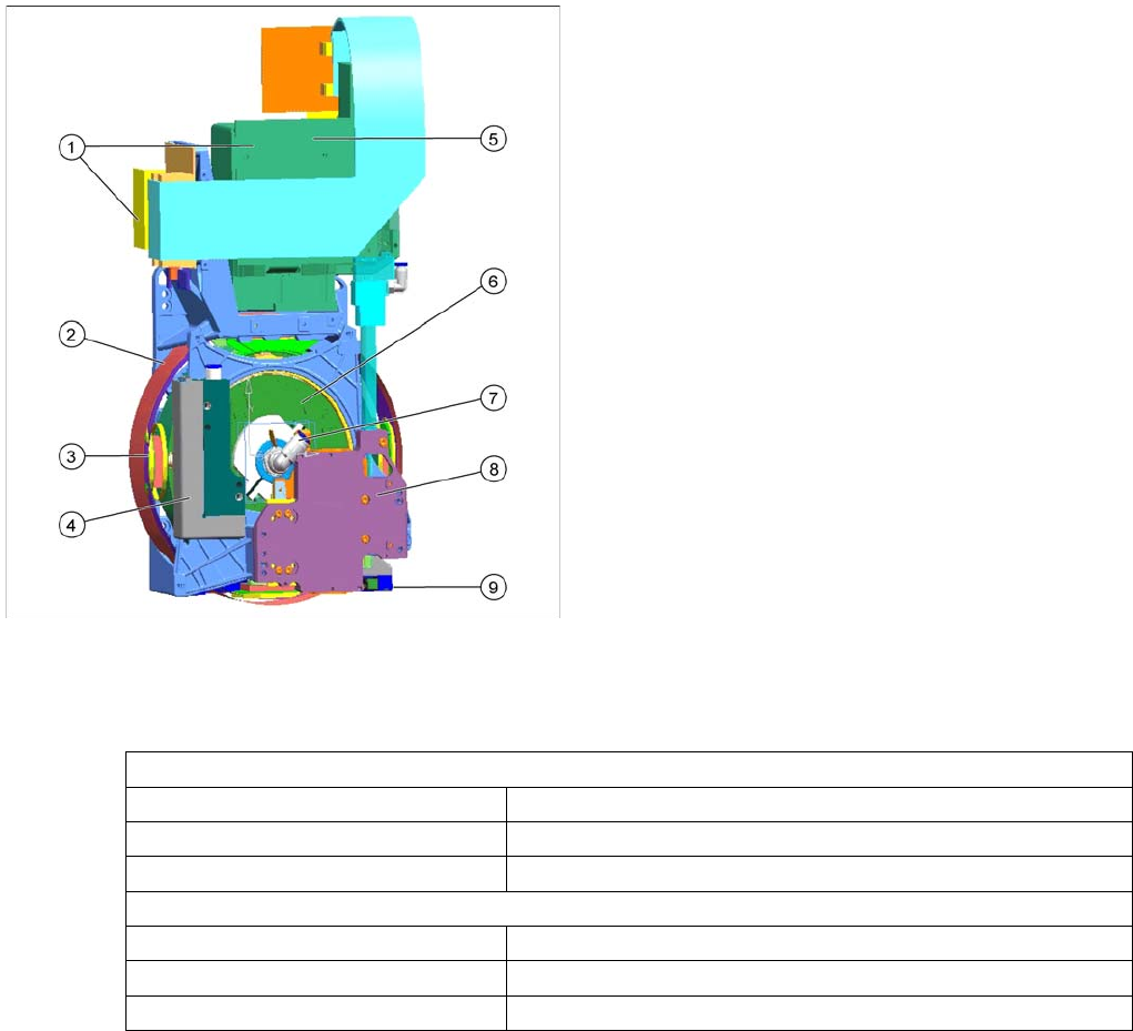
3.2.10.1 Overview
Technical Data
Technical Data
A mixed mode between Collect&Place and Pick&Place is also possible.
Overview of CPP head
CPP placement head with camera SST29
[03070108-xx]
CPP placement head without camera
[03053528-xx]
Legend
1. Intermediate distributors 1 and 2
2. Star motor (integrated into the head housing)
3. DP axis (as direct drive)
4. Pressure control valve
5. Component camera (behind the intermediate
distributor, standard: SST29)
6. Single core solution (SCS) – DP drive control
7. Hold circuit supply, fitted venturi nozzles and valve
switching assembly (valve terminal)
8. Z axis with return cylinder
9. Component sensor in the pick and place position
In Collect&Place mode
Component spectrum 01005 to 27x27 mm, up to 8.5 mm height
Speed Up to 24.000 cph
X/Y accuracy +/- 55 µm for 4 (sigma)
In Pick&Place mode
Component spectrum 01005 to 50x40 mm, up to 11.5 mm height
Speed Up to 1.500 cph
X/Y accuracy +/- 45 µm for 4 (sigma)