00194614-08 Trainingsdoku. SG X-Serie_X4i SW70x (AL2)_EN.pdf - 第322页
TwinHead TwinHead Assemblies Reference Run Student Guide SIPLACE X-Serie and X4I SW70x (AL2) 322 Reference Run 9.2 Reference Run TwinHead Z,D- axes The TwinHead consists of tw o segments which have two axes Z and D and t…
TwinHead
Overview TwinHead Assemblies
321 Student Guide SIPLACE X-Serie and X4I SW70x (AL2)
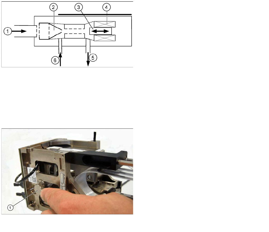
Vacuum Generator Function
After initialization the piston is in a ‘central position’ in which neither vacuum or air kiss is applied to the
nozzle. During pickup the piston is always in the ‘open’ position, in which maximum vacuum is applied
to the nozzle. In the placement cycle the time to switch between maximum vacuum (-850 mbar) to
maximum air kiss (+400 mbar) is < 12ms.
Principle of the vacuum generator
Legend
1. Compressed air input
2. Venturi nozzle
3. Plunger (iron core)
4. Plunger drive (inductor)
5. Discharged air to silencer
6. Vacuum air blast output
Filter for the vacuum system (example of Twin segment
version 03 shown)
Legend
1. Filter for the vacuum system on the Twin- head.
The Filter is mounted on the retract unit and used as an
attenuator to control the vacuum. The filter with the
additional volume reduces the oscillation of the vacuum
generator and guarantees an accurate vacuum and air
blast supply. The filter is serviced at regular intervals,
which must be adhered to (see Maintenance Manual).
TwinHead
TwinHead Assemblies Reference Run
Student Guide SIPLACE X-Serie and X4I SW70x (AL2) 322
Reference Run
9.2 Reference Run
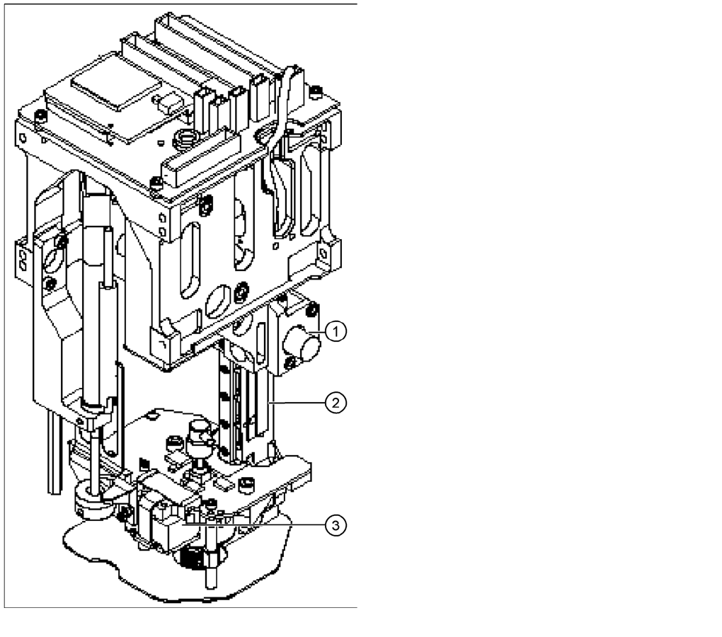
TwinHead Z,D- axes
The TwinHead consists of two segments which have two
axes Z and D and the X and Y axes at the gantry.
Before you start the reference run the return cylinder
move out to the lower home position. On both modules
the vacuum is on, until the vacuum generator is
initialized.
Legend
1. Z axis incremental encoder
2. Z axis linear incremental scale
3. D-axis incremental encoder with incremental glass
scale
TwinHead
Reference Run Reference Run at Z Axis
323 Student Guide SIPLACE X-Serie and X4I SW70x (AL2)
Referen ce Run at Z Axis
9.2.1 Reference Run at Z Axis
Referenc e Run at D- axis
9.2.2 Reference Run at D- axis
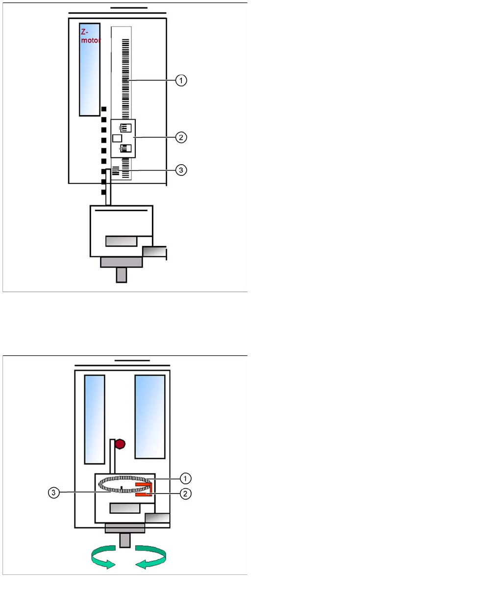
Reference run Z axis
Legend
1. Incremental scale mounted on moveable part of the Z
Axis
2. Fixed Incremental encoder
3. Zero pulse on the incremental scale (only one on the
Z axis)
▪ Z Axis search for the commutation point of the linear
motors (in a special mode because of the danger of a
movement downwards). (A 3 phase motor continues
to run at the correct time and in the correct sequence,
when the current is switched from one phase to the
next one.)
▪ Then the Z Axis move upwards to the Zero pulse and
load the zero point correction.
▪ The zero point correction, max. and min. travel range,
are determined when you calibrate the head height.
Reference run D-axis
Legend
1. Incremental glass scale D-axis
2. Incremental encoder
3. Zero pulse on the incremental glass scale
Then the D-axis (turning axis) executes the reference
run.
The D-axis runs to the zero pulse of the D- axis encoder.
The zero point correction value will be loaded. The D-axis
moves to the reference position, in accordance with the
prefix shown before the value.
Reference run completed! This is followed by the gantry
reference run (see Section Gantry).