00194614-08 Trainingsdoku. SG X-Serie_X4i SW70x (AL2)_EN.pdf - 第77页
Overview Overview of Components Twin Head 77 Student Guide SIPLACE X-Serie and X4I SW70x (AL2) Twin Hea d 3.2.11 Twin Head Description 3.2.11.1 Description Nozzle Chan ger for T win Head 3.2.11.2 Nozzle Changer for Twin …
Overview
CPP Head Overview of Components
Student Guide SIPLACE X-Serie and X4I SW70x (AL2) 76
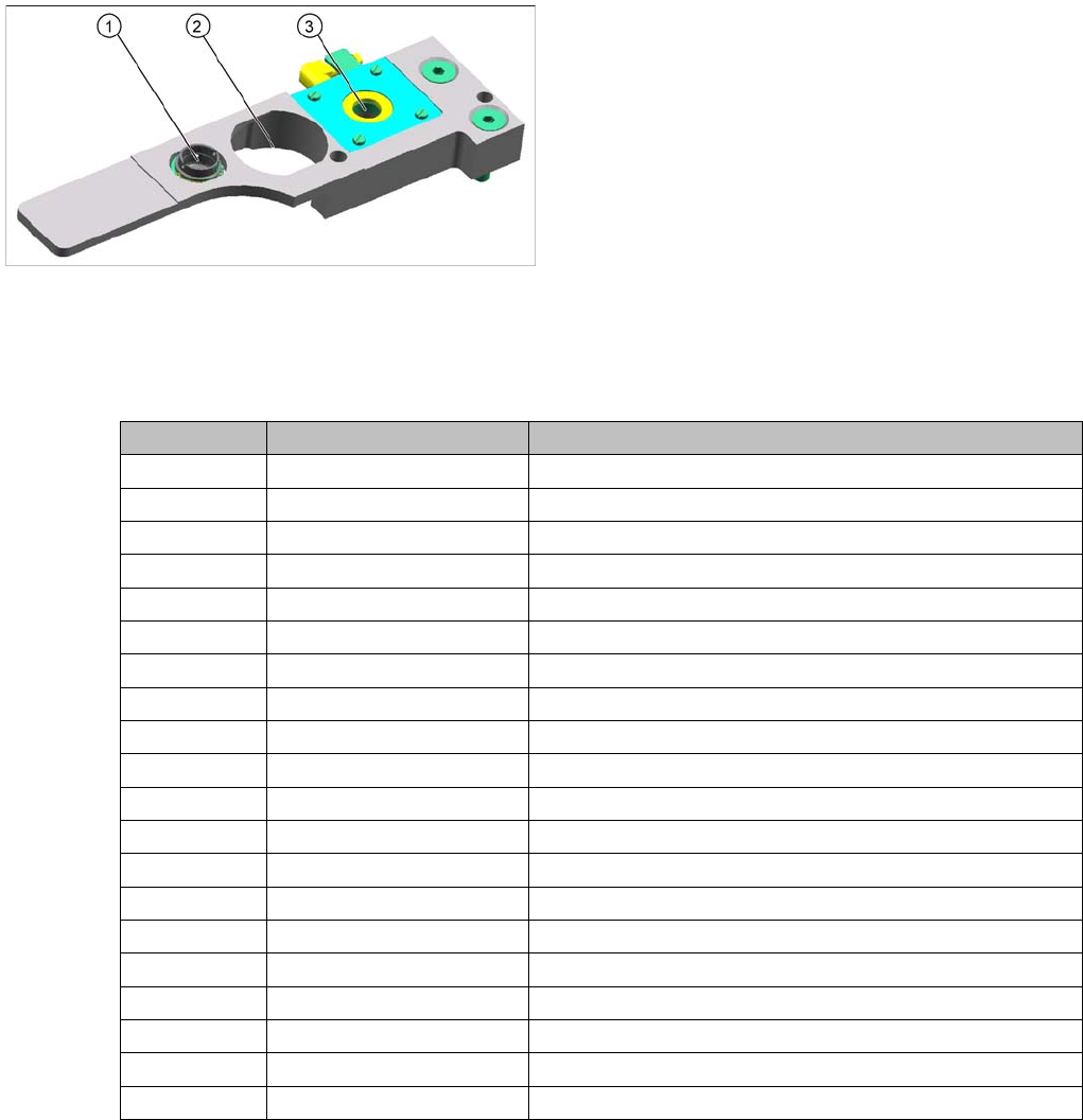
Nozzle Statio n X4I for CPP Hea d
Nozzle Station X4I for CPP Head
Nozzle types
3.2.10.7 Nozzle types
The wide component spectrum available for the CPP head means that two different nozzle series are
needed: 20xx and 28xx.
Legend
1. Take off for 20xx nozzles
2. Take off for 28xx nozzles
3. Reject station for CPP nozzles
Nozzle type Component types Comments
2003 0402
2004 0603, 0805, 1206
2005 01005
2006 0201
2007 0402, 0603
2014 0603, 0805, 1206
2020 PLCC Height: Smaller than 0.75 mm
2021 PLCC Height: Smaller than 4.75 mm
2032 Mini melf, diodes
2033 1206, tantal
2034 Maxi melf, diodes
2035 Tantal C, SO
2036 Mini melf, diodes
2037 SO
2038 Al. Kond.
2039 Al. Kond.
2057 Calibration nozzle
2817 SOX Height: Larger than 0.75 mm, smaller than 4.5 mm
2820 PLCC
2821 PLCC Height: Larger than 4.25 mm, smaller than 8.25 mm
Overview
Overview of Components Twin Head
77 Student Guide SIPLACE X-Serie and X4I SW70x (AL2)
Twin Head
3.2.11 Twin Head
Description
3.2.11.1 Description
Nozzle Changer for Twin Head
3.2.11.2 Nozzle Changer for Twin Head
Twin Head
Legend
1. Module 1
2. Module 2, rotate by 180 ° compared to module 1.
3. Main board on modul 1 and modul 2
4. D Axis
5. Linear motorZ Axis
6. Z axis incremental measurement system
The Twin head consists of two P&P heads of the same
model, which work according to the Pick&Place principle.
The second P&P head is installed on the gantry, at a
rotation of 180 degrees. One component after another
can be picked up per P&P, from the feeder module and
be optically centered by the stationary camera. On the
way to the placement position, the components are
rotated into the correct position. They are then carefully
positioned onto the board, with great precision and with
the help of a regulated air blast and preset force.
Type 5xx nozzles are used for the Twin head. Type 4xx
nozzles for the P&P head and type 8xx and 9xx nozzles
for the C&P heads can be used with an adapter.
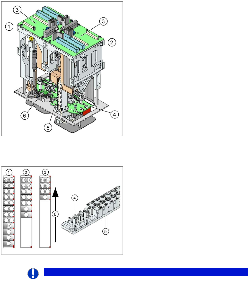
Nozzle Changer for Twin head
SIPLACE X machines, equipped with a Twin head, have
one nozzle changer as a standard. This nozzle changer
is then installed in either sector 3 or sector 1.
The nozzle changer for a Twin head consists of a
standard module with 3 garages, each holding two
standard nozzles and one garage, holding one special
nozzle (see diagram).
Legend
1. Complete Nozzle changer
2. Extended Nozzle changer
3. Standard nozzle changer
NOTICE
If required, the above mentioned configurations can be changed and other magazines for
standard or special nozzles can be added individually.
Overview
Conveyor System Overview of Components
Student Guide SIPLACE X-Serie and X4I SW70x (AL2) 78
Conveyor System
3.2.12 Conveyor System
General
3.2.12.1 General
The SIPLACE X machine is supplied with a PCB single conveyor as standard. A dual conveyor is
available as an option. In its standard version, the SIPLACE X4I is equipped with a PCB dual conveyor.
Depending on your requirements, you can choose the left or right conveyor side as a fixed conveyor side.
In the Processing Area (PA1 or PA2), the PCB board will be clamped from the bottom side against the
fixed holder on the conveyor system. Therefore, the space between the upper side of the board and the
placement head remains the same for each board and no longer depends on the thickness of the board.
This means that the placement performance also no longer depends on the board thickness. The PCB
fiducial centering can also be optimized. Due to the constant (unchanging) distance between the board
upper edge and the PCB camera, the camera is always focussed correctly on the board surface. The
PCB fiducial shape is optimally imaged on the CCD chip of the PCB camera.
The machine height can be adjusted so that the machine can also be integrated into lines with transport
heights of 830, 900, 930 or 950 mm. Communication between the PCB conveyors of the different
machines is provided with the help of a SMEMA or SIEMENS (optional) interface.
The transportation of the boards is monitored and controlled by light barriers, consisting of a transmitter
and a receiver module. Once the board has reached the placement area and the board has been
recognized by the light barrier, the speed of the conveyor belt is reduced. The board is stopped with the
help of a laser beam and is then clamped into place from below.
Clamping
The PCB is lifted for placement of components and pressed up against the PCB clamping rail. When the
lifting table rises the PCB and the complete conveyor drive unit is lifted up to the clamping position. This
method enables the placement surface to remain in the same position, irrespective of the board
thickness.
Boards with a length up to 450 mm (X4I: 380 mm) are clamped into place in the relevant placement area.
Clamping does not take place on the input and output conveyor. However, boards with lengths above
450 mm are placed up to a length of 610 mm on the conveyor belt and are only supported by the lifting
table in the placement area.
Width adjustment
The width is adjusted by means of a motor as programmed. The different widths can be set for conveyor
lanes 1 and 2. The width adjustment uses a stepping motor, meaning that the new PCB width can be set
independently of other machine components (e.g. the Y gantry). There is no proximity switch on the
conveyor side.
The PCB width is adjusted via three adjustment units (pneumatic cylinders), installed under the input,
intermediate and output conveyors in each case. The stepping motor moves the three adjustment units
synchronously through the use of recirculating spindles and a toothed belt.
Board control In the conveyor
The boards are checked with the help of light barriers (transmitter and receiver). The transmitter is
located below the conveyor belt and the receiver opposite to it, above the conveyor belt. The light
barriers stop the board in the input conveyor, intermediate and output conveyors.
The light barrier in the placement areas starts the braking process via the DC motor and switches the
laser (stopper) on. The board moves at reduced speed, within a fixed time window (100 ms) , until it
reaches the stopping position (laser). The braking profile is adjusted to the weight of the board (software-
controlled). This guarantees a consistent transport time, irrespective of the board used