00194614-08 Trainingsdoku. SG X-Serie_X4i SW70x (AL2)_EN.pdf - 第415页
Head Modularity Important Information 415 Student Guide SIPLACE X-Serie and X4I SW70x (AL2) Head Modul arity 12 Head Modularity Importan t Inform ation 12.1 Important Information SIPLACE X and X4I Configuration Op tions …
Modular Conveyor
Conveyor Control TSP 301 Room for Your Sketches and Notes
Student Guide SIPLACE X-Serie and X4I SW70x (AL2) 414
Head Modularity
Important Information
415 Student Guide SIPLACE X-Serie and X4I SW70x (AL2)
Head Modularity
12 Head Modularity
Importan t Inform ation
12.1 Important Information
SIPLACE X and X4I Configuration Op tions
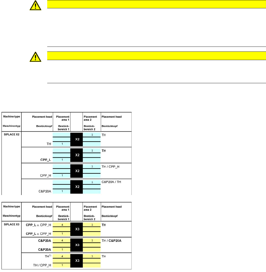
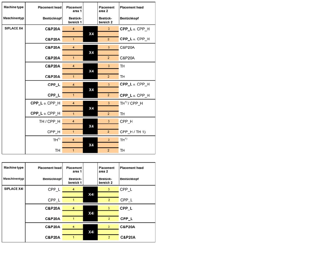
12.2 SIPLACE X and X4I Configuration Options
CAUTION
Head exchange
When replacing the Twin Head with a CPP head with MTC2 in this placement area, you need
to fit a bumper extension, to limit the Y travel range. After switching the machine back on, you
then need to redetermine the machine zero point and the travel ranges.
When you use a Twin Head again, you need to remove the bumper extension.
CAUTION
Risk of head crash!
When installing a CPP head with a stationary camera, this needs to be fitted in the top position,
otherwise there is a risk of a head crash!
Legend
▪ Placement heads
▪ 1/2/3/4 = Gantry 1/2/3/4
▪
1)
: The TH/TH combination in one PA was introduced
with SW 603 and may only be used with the
stationary cameras with VLT33. This also applies to
CPP / CPP or CPP / TH combinations. Retrofitting
kits have been defined to upgrade machines already
in operation.
Head Modularity
Placement Principle SIPLACE X and X4I Configuration Options
Student Guide SIPLACE X-Serie and X4I SW70x (AL2) 416
Placement Principle
12.2.1 Placement Principle
The placement system is based on a torsionally rigid and vibration dampened machine frame made of
cast steel. The placement system has either two (X2), three (X3) or four (X4) gantries. These can be
positioned independently of one another in the X and Y directions, by fast and accurate linear motors.
Each gantry is equipped with a placement head.
Two placement head variants are used:
▪ The Collect&Place procedure for components from size 01005 to fine pitch with a CPP head with 12
segments or with a C&P20A head with 20 segments.
▪ The Pick&Place procedure with one Twin head for fine pitch/super fine pitch components
The head modularity principle developed by SIPLACE allows you to change placement heads quickly
and easily.
Four locations are available for supplying the components. A maximum of four component trolleys or two
Matrix Tray Changers (MTC) can be used.
The station software 70x supports the C&P20A, CPP, TH and high force TH placement heads with X
feeders. A combination of S feeders and DLM heads is not possible!
Depending on the machine type, one or two gantries are operated in placement area 1 (gantries 1/4) and
placement area 2 (gantries 2/3), each with one placement head.
This picks up the components from the feeders which are on a stationary component trolley.
There are two methods of component placement:
SIPLACE X4I - Configuration