00194614-08 Trainingsdoku. SG X-Serie_X4i SW70x (AL2)_EN.pdf - 第57页
Overview Overview of Components Changeover Table Com ponents 57 Student Guide SIPLACE X-Serie and X4I SW70x (AL2) Axis Con troller Board A364 3.2.5.2 Axis Controller Board A364 Changeover Table Co mponents 3.2.6 Changeov…
Overview
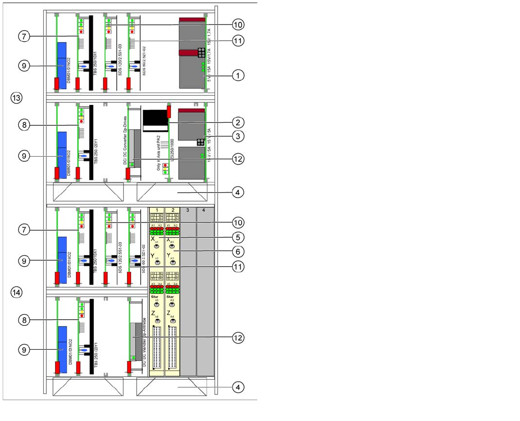
Axis Unit with A364 Overview of Components
Student Guide SIPLACE X-Serie and X4I SW70x (AL2) 56
Axis Unit A364
3.2.5.1 Axis Unit A364
See also
12.9.1 Axis Unit A364 [ ➙ 429]
Configuration of axis unit X4I with C&P20A heads
Legend
1. Power supply +/- 15, +5 V
2. Ballast circuit, only in axis unit PA2
3. Power supply +/- 15V
4. Fan unit (blows downwards)
5. Axis card A364 for gantry 1/2
6. Axis card A364 for gantry 4/3
7. Servo amplifier X axes
8. Servo amplifier Y axes
9. Brake board for each X axis and Y axis
10. Servo star axis (2x)
11. Servo Z axis (2x)
12. DC/DC converter DP drives (2x)
13. Placement area 1 gantry 1 (top half)
14. Placement area 1 gantry 4 (bottom half)
Overview
Overview of Components Changeover Table Components
57 Student Guide SIPLACE X-Serie and X4I SW70x (AL2)
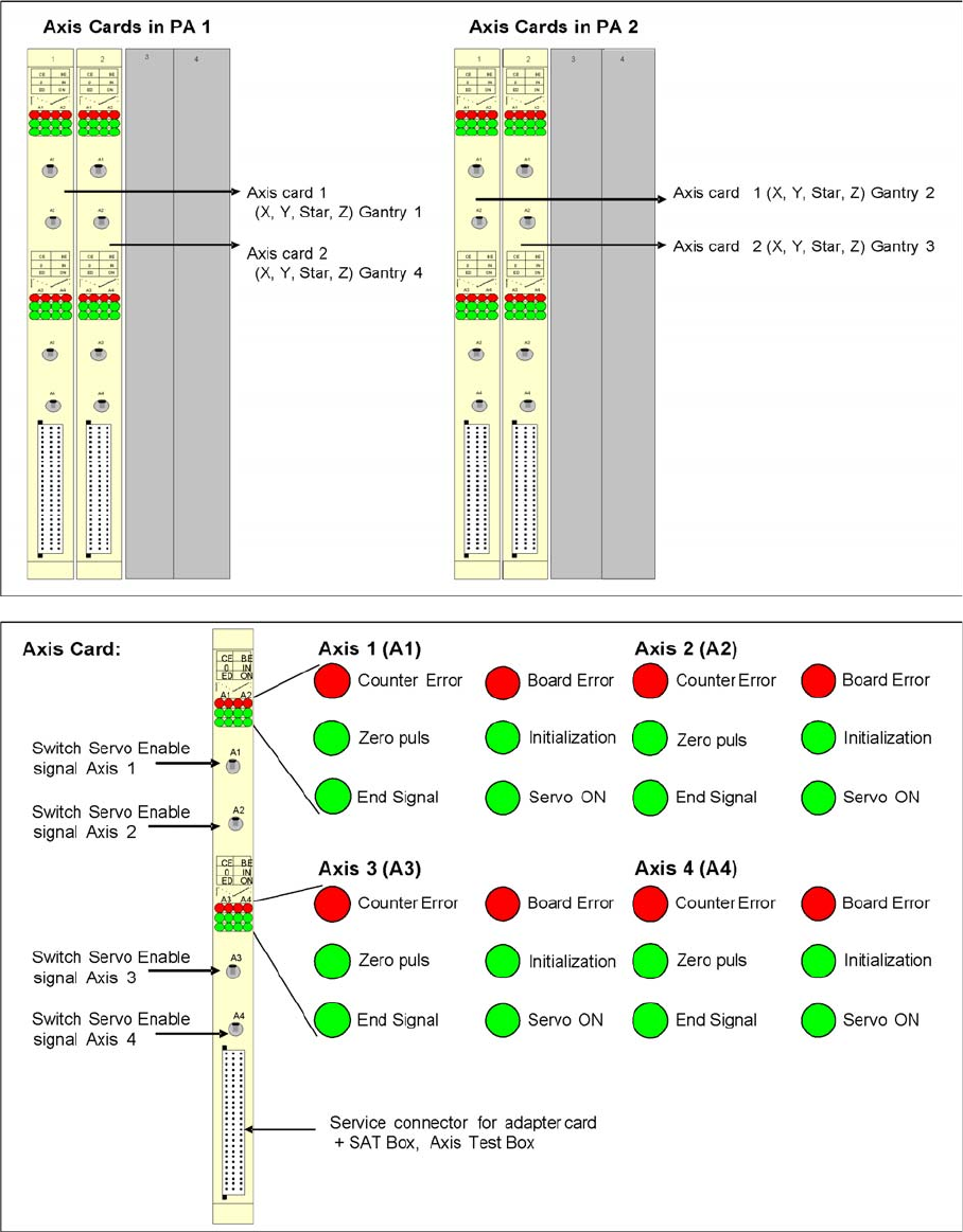
Axis Con troller Board A364
3.2.5.2 Axis Controller Board A364
Changeover Table Components
3.2.6 Changeover Table Components
SIPLACE X machines with SW70x only support the new generation of X feeders and X component
changeover tables. This changeover table does not have any electronic assemblies, such as the
communication unit for feeder supply and control in the previous tables. The power supply for the feeders
is without contact, via an inductive interface on the docking unit, directly to the feeders. Control and
Overview
Changeover Table Components Overview of Components
Student Guide SIPLACE X-Serie and X4I SW70x (AL2) 58
communication between the feeder control unit (FCU) and the feeders is provided via two optoelectronic
channels (light conductors). The FCU is connected to the computer unit in the machine via the machine
CAN Bus. Only X tables can be used on the machines.
Docking and Undocking
3.2.6.1 Docking and Undocking
Each X feeder table has 40 slots for 8 mm X feeders, giving a total capacity of 160 individual tracks on
4 changeover tables.
Setting the Height of the Changeover Table
3.2.6.2 Setting the Height of the Changeover Table
Shows the button for docking and undocking changeover
tables
Legend
1. Button for docking and undocking changeover tables
▪ T = transport direction
The changeover table is automatically docked at the
machine, with two pneumatic cylinders. For docking, the
changeover table is moved up to the docking unit, the
hood is closed and the button is pressed. For undocking,
the cover is opened and the button is pressed again.
NOTICE
From software 70x
X machines from software 70x only support X tables.
NOTICE
X4I
Due to the rotated gantries, there are only 34 tracks available at locations 2 and 4 of the X4I.
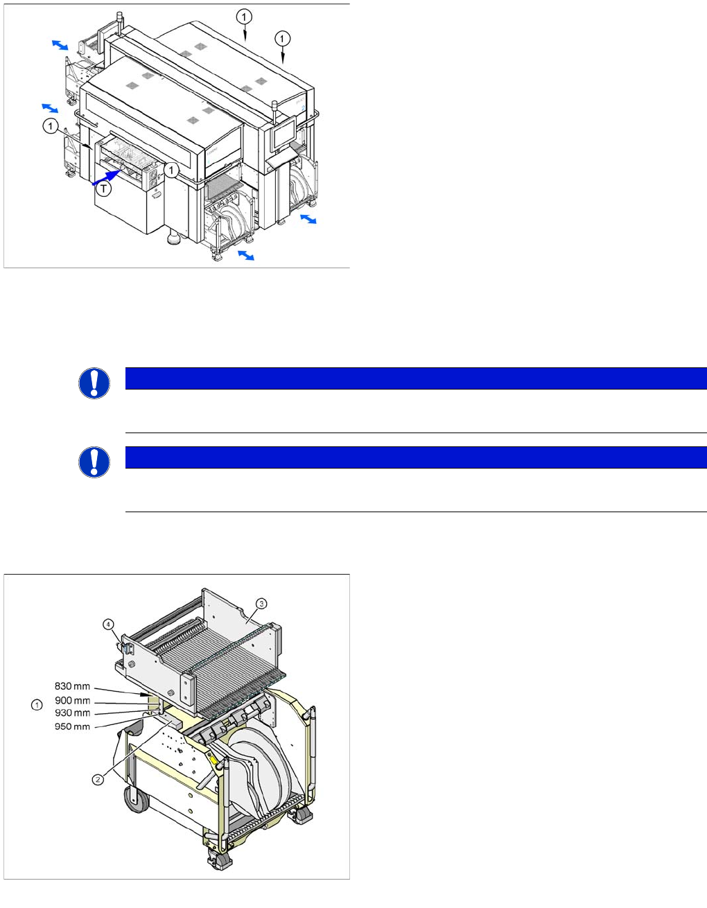
Component table for X feeder
Legend
1. Drillings for the various PCB conveyor heights,
adjustment via insertion of a spring pin.
2. Contact surface (block) for the upper part of the table
3. Changeover table
4. Reed switch for closing the safety circuit to the
docking unit