00194614-08 Trainingsdoku. SG X-Serie_X4i SW70x (AL2)_EN.pdf - 第48页
Overview Configurations SIPLACE X Series Student Guide SIPLACE X-Serie and X4I SW70x (AL2) 48 SIPLACE X2 Conf iguration 3.1.2.5 SIPLACE X2 Configuration SIPLACE X4I - Co nfiguration 3.1.2.6 SIPLACE X4I - Configuration Th…
Overview
SIPLACE X Series Configurations
47 Student Guide SIPLACE X-Serie and X4I SW70x (AL2)
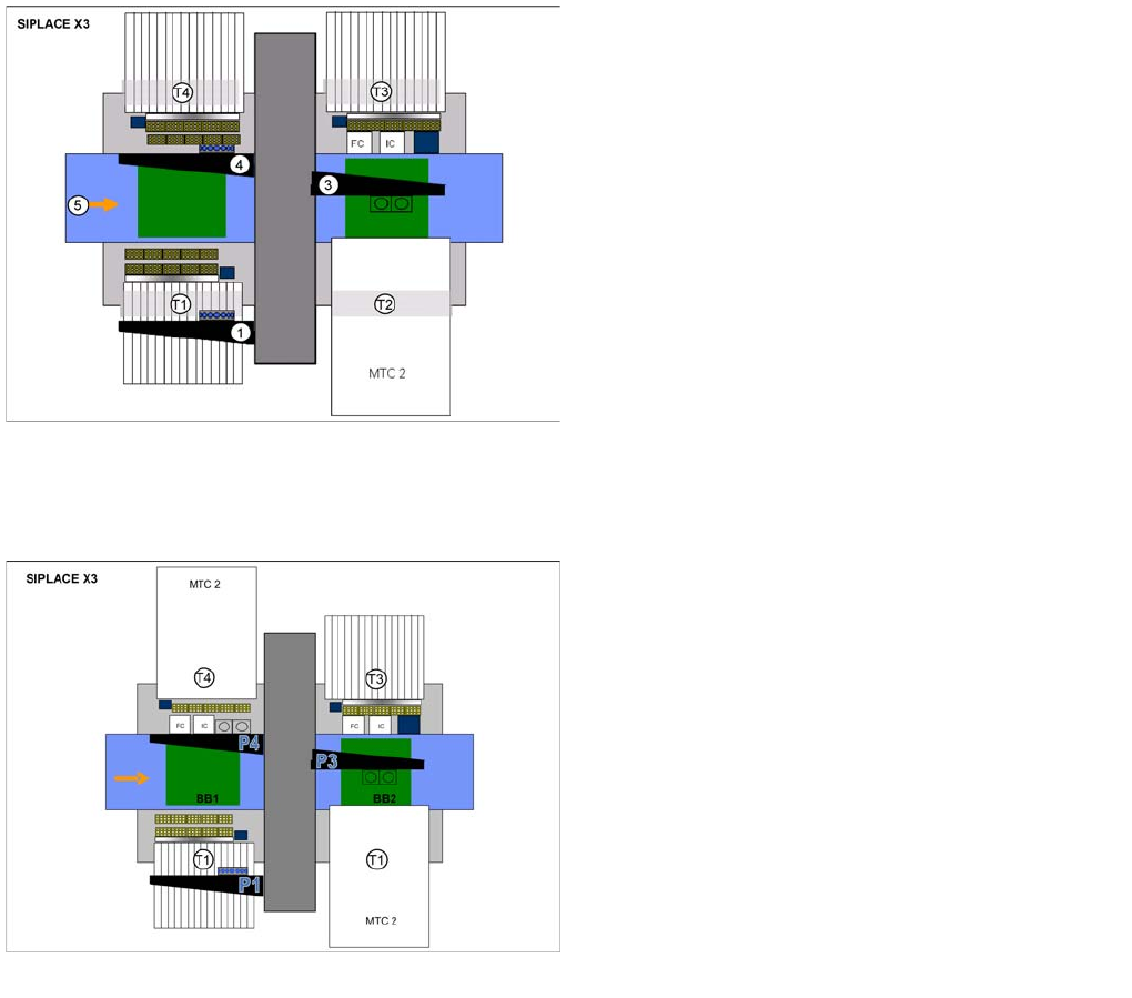
SIPLACE X3 with 1 MTC2 - Configu ration
3.1.2.3 SIPLACE X3 with 1 MTC2 - Configuration
SIPLACE X3 wi th 2 MTC2 - Co nfiguration Optio ns
3.1.2.4 SIPLACE X3 with 2 MTC2 - Configuration Options
SIPLACE X3 configuration options
Legend
▪ Dimensions (L x W) 2.38 x 2.75 m
▪ 1, 3, 4: Gantry 1, 3, 4
Gantry 1 and 4 with CPP, C&P20A or Twin Head
Gantry 3 with CPP or Twin Head
▪ T1 - T4: Locaton 1 - 4
Location 1, 3, 4: 40 tracks for 8 mm X feeder
Location 2: Changeover table or MTC2
▪ 5: Direction of transport , PCB conveyor with 5 areas
SIPLACE X3 configuration options
Legend
▪ Dimensions (L x W) 2.38 x 2.75 m
▪ 1, 3, 4: Gantry 1, 3, 4
Gantry 1 and 4 with CPP or Twin Head
Gantry 3 with CPP or Twin Head
▪ T1 - T4: Locaton 1 - 4
Location 1, 3, 4: 40 tracks for 8 mm X feeder
Location 2: Changeover table or MTC2
▪ 5: Direction of transport , PCB conveyor with 5 areas
Overview
Configurations SIPLACE X Series
Student Guide SIPLACE X-Serie and X4I SW70x (AL2) 48
SIPLACE X2 Conf iguration
3.1.2.5 SIPLACE X2 Configuration
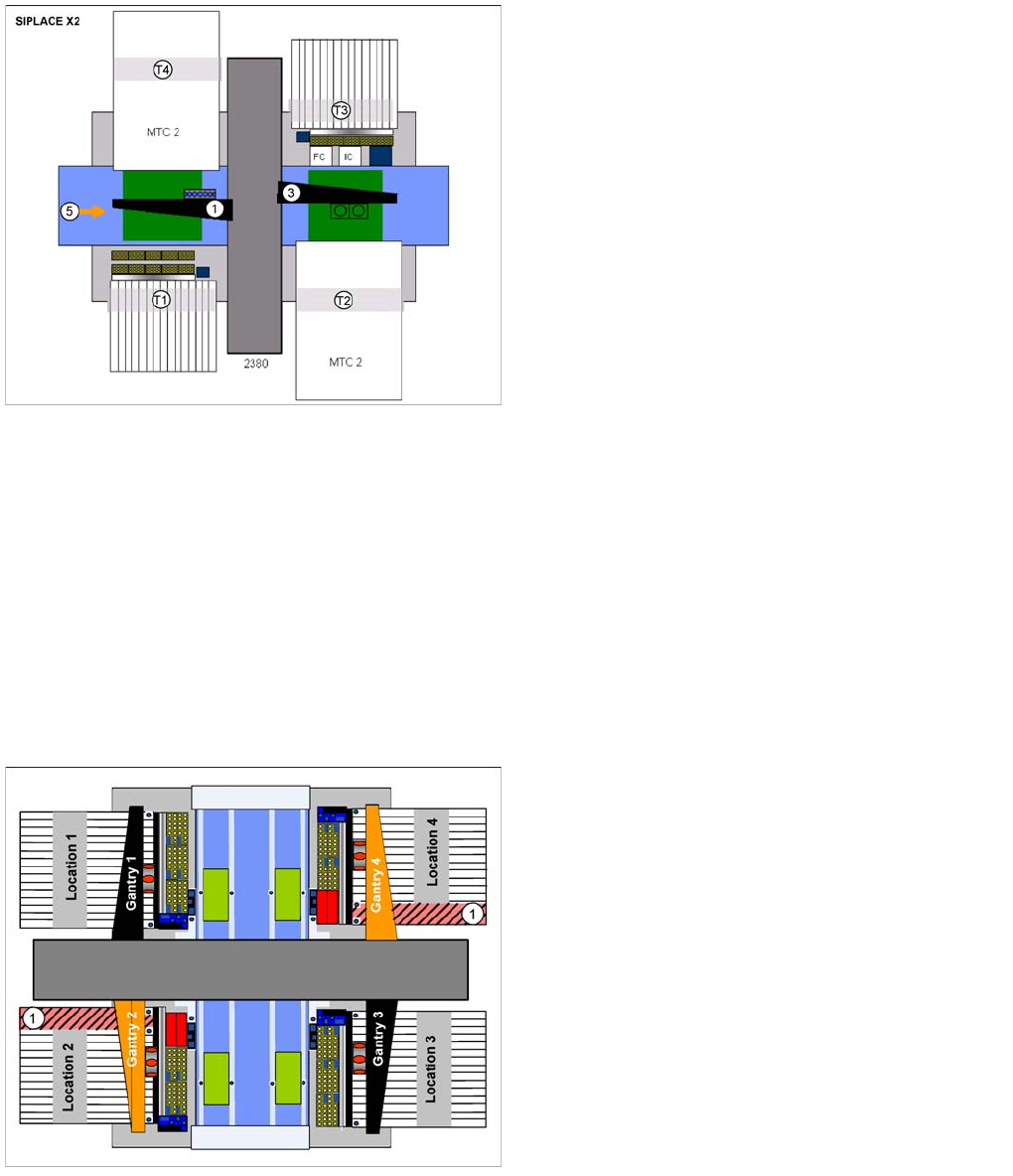
SIPLACE X4I - Co nfiguration
3.1.2.6 SIPLACE X4I - Configuration
The machine is designed and configured for the best possible placement performance. The standard
configuration therefore has 4 gantries, each with one C&P20A placement head. Travel range
optimization has been achieved by rotating gantries 2 and 4. This also enables both gantries to work
independently of one another in the same placement area: I-placement mode.
The following options can be used to further reduce the cycle time in the placement line:
▪ The combined PCB function
▪ A third conveyor lane with shuttle, to replace the productivity lift
▪ A conveyor with 4 lanes (quad lane)
SIPLACE X2 configuration options
Legend
▪ 1, 3: Gantry 1, 3
Gantry 1 with CPP, C&P20A or Twin Head
Gantry 3 with CPP, C&P20A or Twin Head
▪ T1 - T4: Locaton 1 - 4
Location 1, 3: 40 tracks for 8 mm X feeder
Location 2, 4: Changeover table or MTC2
▪ 5: Direction of transport , PCB conveyor with 5 areas
Placement area 2 is always equipped with one placement
head which can place higher components than
placement area 1.
Legend
1. Prohibited areas
Due to the rotated gantries 2 and 4, the marked areas
can not be reached. This applies with both C&P20A
and CPP head configurations.

Overview
SIPLACE X Series Siplace X Series Specifications (Excerpt)
49 Student Guide SIPLACE X-Serie and X4I SW70x (AL2)
Siplace X Series Specifications (Excerpt)
3.1.3 Siplace X Series Specifications (Excerpt)
Specification details Value
Placement performance with example of X4i with C&P20A
Benchmark 120.000 cph
Theoretical value 135.000 cph
IPC value 102.000 cph
C&P20A placement head
Component spectrum 01005 to 2220, Melf, SOT, SOD
Component dimensions (LxW) 6x6 mm
CO height 4.0 mm
CO weight 1 g
Placement accuracy X/Y accuracy:
± 41 μm (3 sigma); ± 55 μm (4 sigma)
Angle accuracy
± 0.5° / (3 sigma); ± 0.7° / (4 sigma)
Placement force 1.5 -4.5 N
Placement mode Collect and Place
Placement performance (benchmark) 30.000 cph
TwinHead placement head
Component spectrum 0201 to SO, PLCC, QFP, socket, connector, BGA, Bare
Die, Shield, FlipChip
Component dimensions (LxW)
in operation with one segment 85x85 mm (125x10 mm)
in operation with both segments 50x50 mm (69x10 mm)
CO height 25 mm
CO weight 30 g, max.100 g
Placement accuracy X/Y accuracy:
± 26 μm / 3σ, ± 35 μm / 4σ ± 22 μm / 3σ, ± 30 μm / 4σ
Angle accuracy
± 0.05° / 3σ, ± 0.07° / 4σ ± 0.05° / 3σ, ± 0.07° / 4σ
Placement force 1-15 N, max.30 N High Force TH
Placement mode Pick and Place
Placement performance (benchmark) 5.000 cph
CPP placement head
Component spectrum 0201 to SO, PLCC, QFP, socket, connector, BGA, Bare
Die, Shield, FlipChip
Component dimensions (LxW) 32x32 mm (C&P mode), 50x40 mm (P&P mode)
CO height CPP_L 6.0 mm, CPP_H 8.5-11.5 mm
CO weight 4 g in C&P mode, 8 g in P&P mode
Placement accuracy ± 55 µm / 4 sigma in C&P mode,
± 45 - ± 55 µm / 4 sigma depending on component camera
(mixed mode)
± 45 µm /4 sigma in P&P mode
Placement force 1-10 N
Placement mode Collect and Place, mixed mode, Pick and Place
Placement performance (benchmark) 23.500 cph in C&P mode, 15000 cph in P&P mode