00194614-08 Trainingsdoku. SG X-Serie_X4i SW70x (AL2)_EN.pdf - 第312页
Collect, Pick and Place Head (CPP) Calibrating the Segment Offset Settings on the CPP Head Student Guide SIPLACE X-Serie and X4I SW70x (AL2) 312 Conversion Calibratin g the Se gment Off set 8.5.3 Calibrating t he Segment…
Collect, Pick and Place Head (CPP)
Settings on the CPP Head Converting the CPP Head for a Different Head Height
311 Student Guide SIPLACE X-Serie and X4I SW70x (AL2)
Convertin g the CPP Head fo r a Different Head Height
8.5.2 Converting the CPP Head for a Different Head Height
Overview
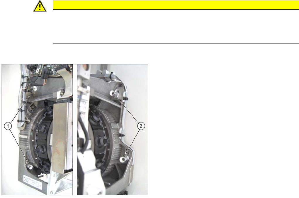
CAUTION
The placement head can be installed on two different heights. CPP_L corresponds to a
component height of 6 mm. CPP_H corresponds to a component height of 11.5 mm.
If the CPP head is used in a placement area with stationary camera, TwinHead or MTC, it may
only be used in the upper position.
Legend
1. Fastening screws on the left side
2. Fastening screws on the right side
In this graphic the fastening screws are shown in the
"head top" position.
Collect, Pick and Place Head (CPP)
Calibrating the Segment Offset Settings on the CPP Head
Student Guide SIPLACE X-Serie and X4I SW70x (AL2) 312
Conversion
Calibrating the Segment Offset
8.5.3 Calibrating the Segment Offset
► Switch over to the operator level Machine Service.
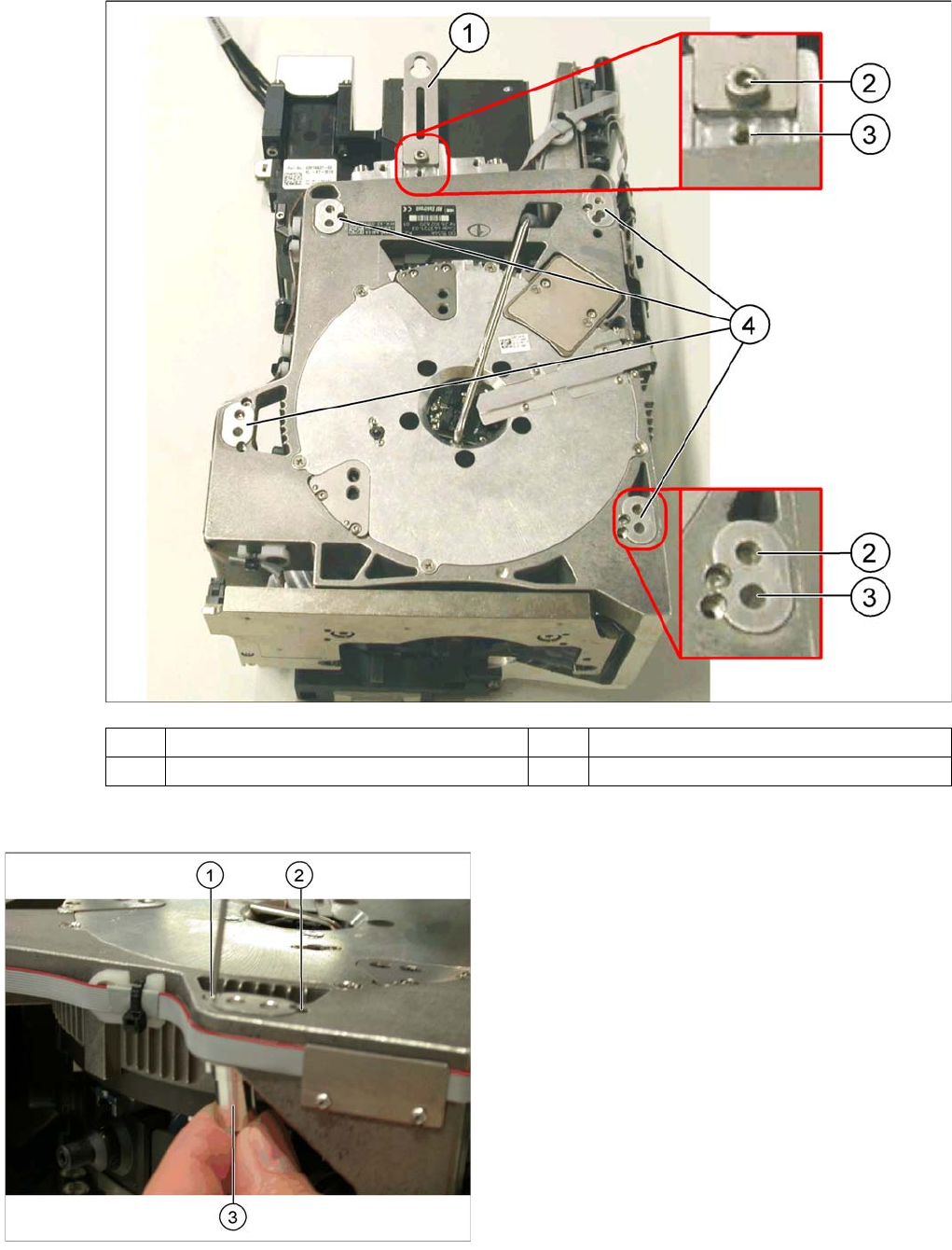
(1) Holding bracket (2) "Head bottom" position
(3) "Head top" position (4) Fixture holes with bushings
Legend
1. Drilling for the fastening screw of the bushing in "head
bottom" position
2. Drilling for the fastening screw of the bushing in "head
top" position
3. Bushing"
All four bushings must either be fixed in top or bottom
position.
Proceed as follows when replacing the bushings:
► Undo the fastening screws of the bushings.
► Insert the bushings in the correct position and re-
tighten them.
► Perform these steps for all four bushings and the
holding bracket of the head.
Collect, Pick and Place Head (CPP)
Nozzle Changer Calibrating the Segment Offset
313 Student Guide SIPLACE X-Serie and X4I SW70x (AL2)
► Select Service (Configure, update and calibrate the machine) .
► Select Single calibration.
► Select Head calibration.
► Select Calibrate segments...
► Select the segments to be calibrated and then click on Start calibration.
Nozzle Changer
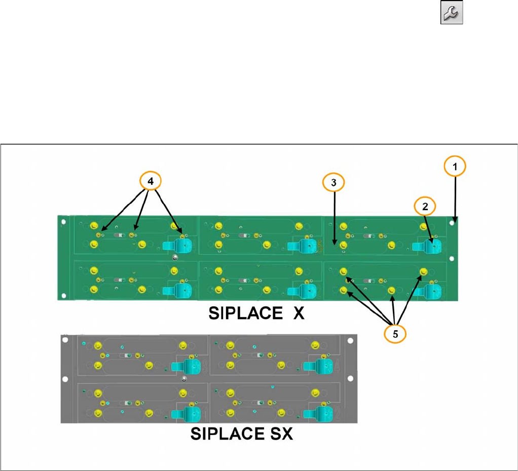
8.6 Nozzle Changer
1. Nozzle changer frame
2. Push button for NC magazine release.
3. Actuator to open and close the NC magazines via software.
4. Monitor NC magazines, switches 1, 2 & 3.
5. Spring pins to mount the NC magazines.
Nozzle changer SX and X Machine
On the NC frame of the SX-machine you can mount 4 magazines with twelve 20xx nozzles or eight 28xx
nozzles. All together a maximum of four nozzle changers can be install on one location, so that you can
have 16 magazines.
On the X-series machine a maximum of two nozzle changer rows with 6 magazines per row can be
mounted on one location. With the X4i only one row per location is possible.
The mechanical construction and function of both nozzle changer are the same, but with additional
functionality:
▪ Recognition the type of magazine
▪ Height monitoring of the magazines
▪ The status of the switches will be checked after switching ON the machine and when the machine
cover is closed.