00194614-08 Trainingsdoku. SG X-Serie_X4i SW70x (AL2)_EN.pdf - 第342页
TwinHead Parameter and Calibrations Settings Student Guide SIPLACE X-Serie and X4I SW70x (AL2) 342 Calibrati ng the Closed Vac uum Calibrating the Closed Vacuum Calibratio n of the TwinHead and Came ra Offset s Calibrati…
TwinHead
Settings Parameter and Calibrations
341 Student Guide SIPLACE X-Serie and X4I SW70x (AL2)
See also
9.4.2.2.3.1 Automatically Determining the DP Axis Zero Point Correction [ ➙ 339]
Setting the Pr essure Control Valve
Setting the Pressure Control Valve
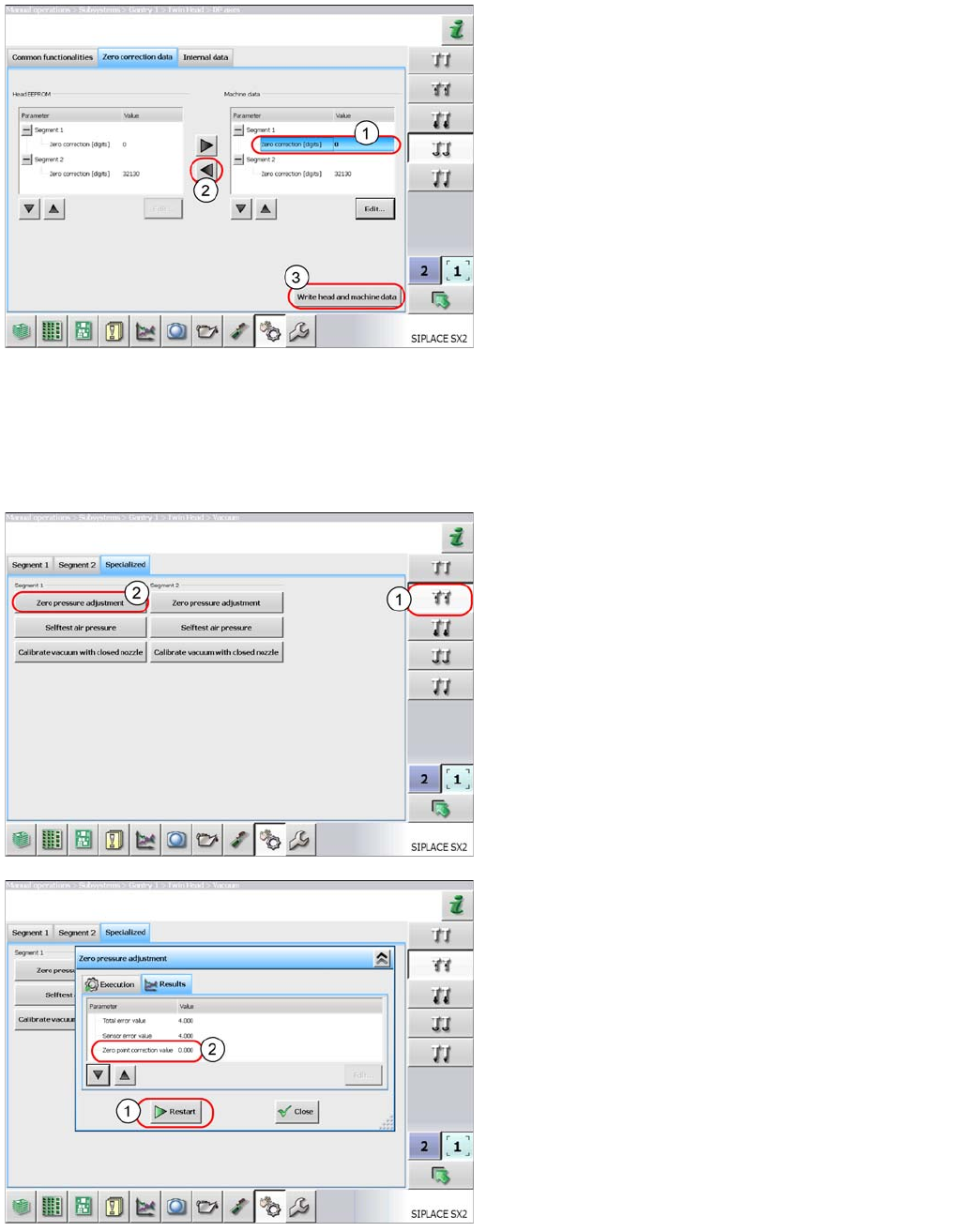
► Select Zero correction data and enter this
value in the Zero correction field (1) of the
relevant segment.
► Select the button (2) to apply the value to the head
EEPROM.
► Select Write head and machine data (3) to
save the value.
► Perform Reference head axis.
The nozzle should now be parallel to the conveyor edge.
► Perform automatic zero point correction of the DP
axis.
► Select the button shown (1).
► Select Zero pressure adjustment (2). This
switches the machine compressed air off and
measures the ambient pressure at the nozzle. The
pressure control valve is therefore set to the ambient
pressure. This is important when machines which are
installed at high altitudes need to be operated in
relation to sea level.
As a result, you will be issued with a zero point correction
value for the pressure control valve.
This function can be repeated with the
Restart button(1).
The zero point correction value should be 0 +/- 10.
TwinHead
Parameter and Calibrations Settings
Student Guide SIPLACE X-Serie and X4I SW70x (AL2) 342
Calibrati ng the Closed Vac uum
Calibrating the Closed Vacuum
Calibration of the TwinHead and Camera Offsets
Calibration of the TwinHead and Camera Offsets
The final calibrations that are required after a new TwinHead has been fitted to a machine involve the
calibration of the head and camera offsets.
Calibration Step 1
Calibration Step 1
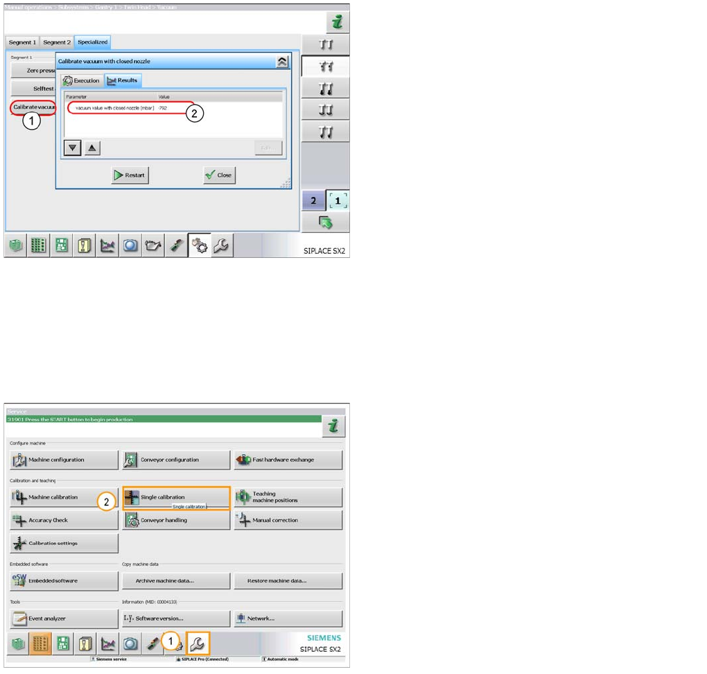
You need a 518 nozzle for this function.
► Select the button Calibrate vacuum with
closed nozzle (1). The gantry moves over the
fixed conveyor side and moves the Z axis
downwards. When the nozzle touches the conveyor
side, a closed nozzle vacuum will be measured. A
vacuum value in mbar will be shown as a result (2).
This depends on the machine installation site, in
relation to sea level.
1. Select the ‘Service’ menu.
2. Select ‘Single Calibration’ menu.
TwinHead
Settings Parameter and Calibrations
343 Student Guide SIPLACE X-Serie and X4I SW70x (AL2)
Calibration Step 2
Calibration Step 2
Calibration Step 3
Calibration Step 3
Calibration Step 4
Calibration Step 4
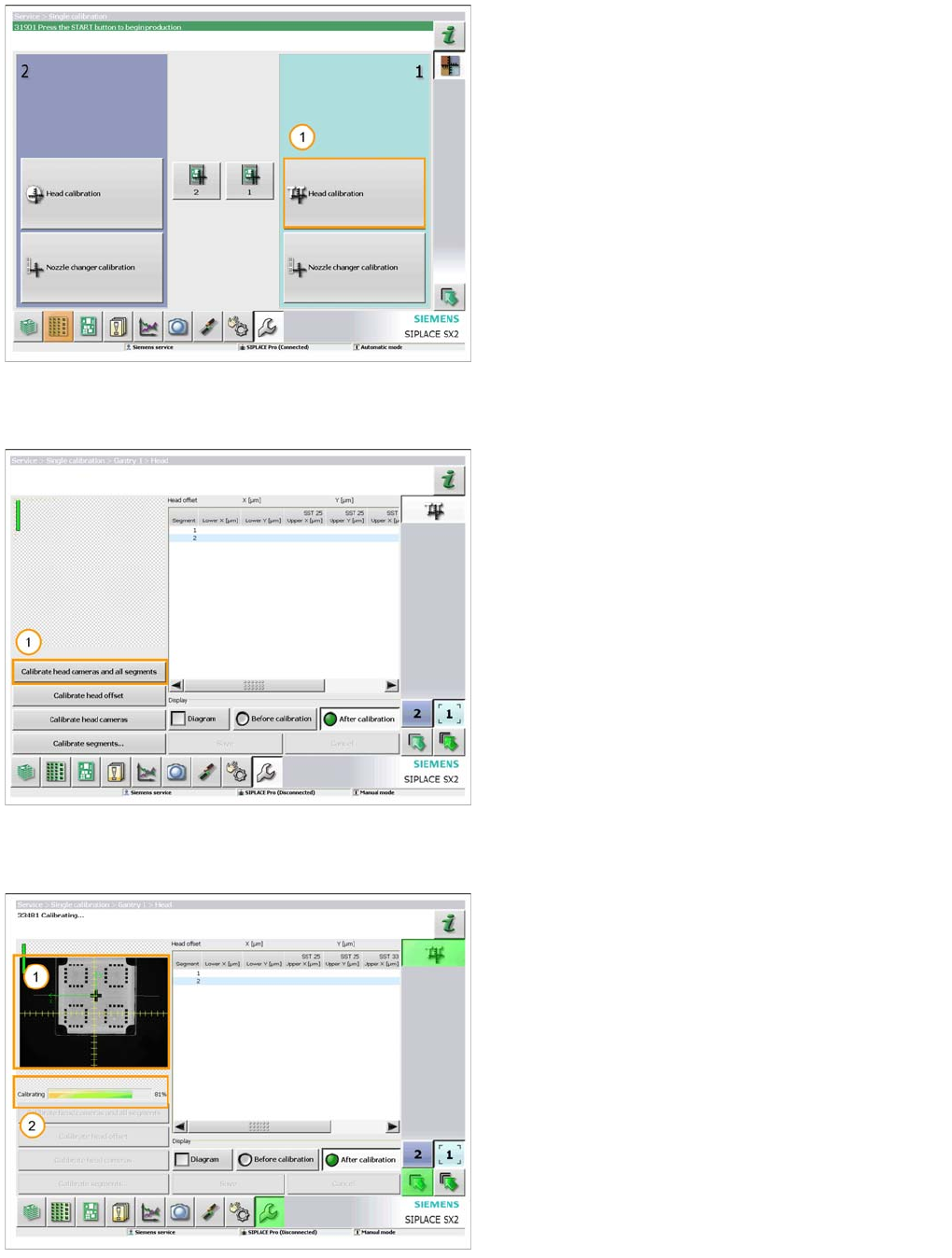
1. Select ‘Head calibration’ for the gantry fitted with the
TwinHead.
A 518 nozzle should now be fitted to both segments on
the head and the calibration tool should be placed in the
pocket on the conveyor rail.
1. When you are ready select ‘Calibrate head cameras
and all segments’.
The calibration will now be automatically performed. It will
take approx. 5 minutes.
1. The image from the vision system is displayed as the
calibration takes place.
2. The progress of the calibration is also displayed.