00194614-08 Trainingsdoku. SG X-Serie_X4i SW70x (AL2)_EN.pdf - 第294页
Collect, Pick and Place Head (CPP) Placement Modes Pickup and Placement Cycle for CPP Student Guide SIPLACE X-Serie and X4I SW70x (AL2) 294 Pick&P lace Mode 8.4.2.2 Pick&Place Mode The Pick and Place mode is the …
Collect, Pick and Place Head (CPP)
Pickup and Placement Cycle for CPP Placement Modes
293 Student Guide SIPLACE X-Serie and X4I SW70x (AL2)
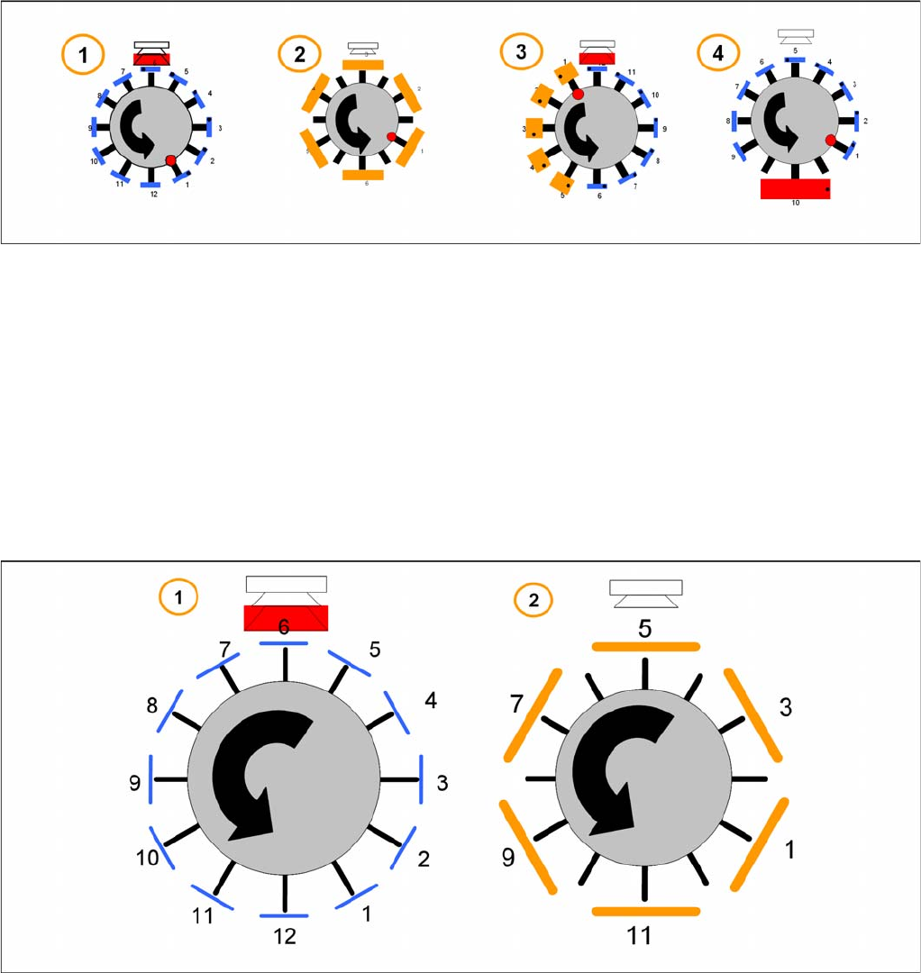
Example
1. Collect and Place mode for small components only.
2. Collect and Place mode (with skipped segments) for medium components.
3. Mixed mode – collect and place for small components, pick and place for high components.
4. Mixed mode – collect and place for small components and pick and place for 1 large component.
The placement mode is dependent on the configured component camera and the component size with
their tolerance in SIPLACE Pro. It is automatically selected by the optimization software.
Collect&Place Mode
8.4.2.1 Collect&Place Mode
The Collect and Place Mode is the same mode as used by the existing C&P6/12 and C&P20 heads.
According to the number of available segments we pick up the component, center them and then place
them.
1. For the standard Collect and Place Mode, the max. component size is dependent on the camera
configuration (SST.29 & 38).
2. Components with a size up to 32 x 32 mm ( include the tolerance in SIPLACE Pro) can be picked up
and turned by the head. But they have to be centered with a stationary camera.
Collect, Pick and Place Head (CPP)
Placement Modes Pickup and Placement Cycle for CPP
Student Guide SIPLACE X-Serie and X4I SW70x (AL2) 294
Pick&Place Mode
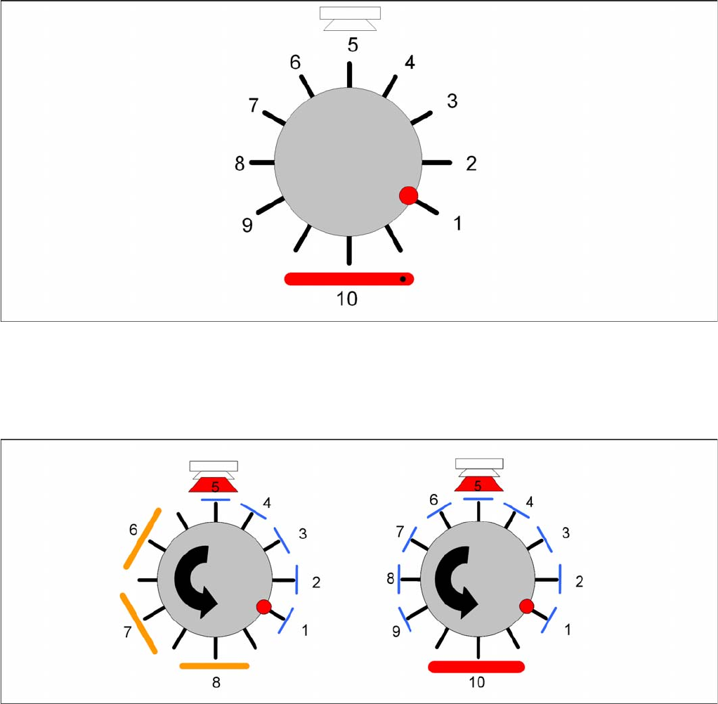
8.4.2.2 Pick&Place Mode
The Pick and Place mode is the same as used by the previous IC and TwinHeads. We pick up one
component with one segment, move to the stationary camera and center the components. The
component will be placed in the correct x/y- and angle-position.
Mixed Mode
8.4.2.3 Mixed Mode
According to the number of available segments the head will pick up the components and turn the them
through the head. Dependent on the component size and camera type the head will center the
components with the component camera whilst all other larger components will be centered with the
stationary camera. These components will be placed first according to some special features and
restrictions.
The follow special features and restrictions will be optimized in SIPLACE Pro:
▪ Component covered component sensor (Nozzle + Component height at 18,5mm)
▪ Dependency between Component size and weight and the camera types
▪ The placement shadow with components of max.11,5mm height.
▪ Travel profiles of the components (for Star, Dp- and Z-drives)
▪ Overlap Z and Star axis (e.g. 01005, big and flat components)
Collect, Pick and Place Head (CPP)
Pickup and Placement Cycle for CPP Board Position Recognition
295 Student Guide SIPLACE X-Serie and X4I SW70x (AL2)
Board P osition Re cognition
8.4.3 Board Position Recognition
We differentiate between standard position recognition and dual position recognition.
PCB – position recognition (standard position recognition)
Board position recognition is used to determine the exact position of the board in the machine (conveyor
--> placement area).
PCB position recognition is performed with gantry 4 for placement area 1 and with gantry 2 in placement
area 2.
There should be at least two fiducials on each PCB. These are then used to calculate the X/Y position
and the rotary angle of the board, in the conveyor system.
The fiducials should not be on the same line.
Up to 3 fiducials can be programmed for position recognition. With this third fiducial you can also
determine and correct any displacement within the board (shrinkage, stretched).
Dual position recognition (for alternating mode only)
Dual position recognition is required in order to guarantee the placement accuracy. Materials change
according to the temperature they are subjected to and the same applies to the machine gantries.
Dual position recognition is performed with gantry 1 in placement area 1 and with gantry 3 in placement
area 2.
In the case of dual position recognition, gantry 1/3 uses the fiducial position recognition values from
gantry 2/4 to calculate the placement offset for gantry 1/3. Depending on the arrangement of fiducials on
the board, either 2 or 3 fiducials will be used for dual position recognition.
The fiducials for dual position recognition are selected so that the calculation performed can be as
accurate as possible.
Temperature compensation
A further measure to ensure placement accuracy is the temperature compensation with the help of
sensors on the head plate. The head plate features two temperature sensors, the temperature values of
which are regularly checked via a separate bus system.
The software uses these temperature values to calculate an offset value, which is added to the head
offset.
▪ Head offset SW 60x is the distance PCB <--> component camera
▪ Head offset SW 70x is the distance PCB camera <--> nozzle tip
▪ The temperature reference value is the temperature during the last machine calibration.
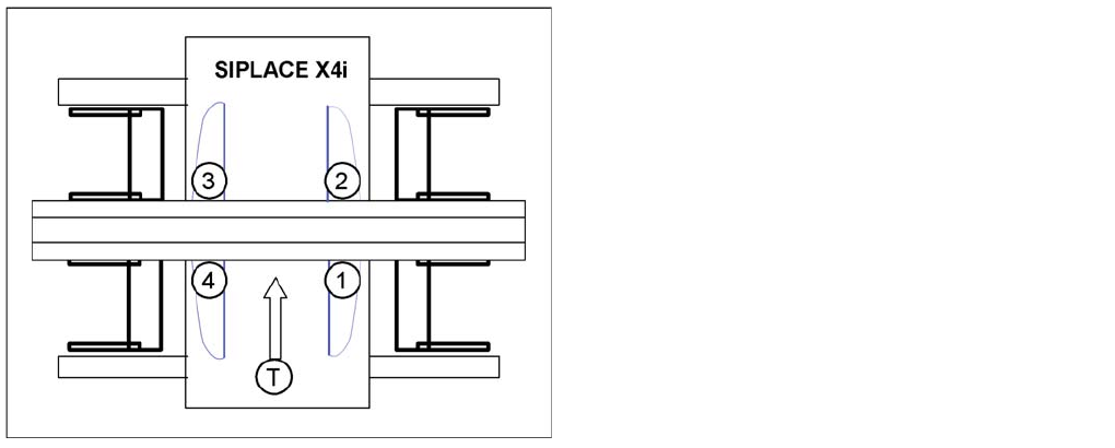
SIPLACE X4I:
▪ Gantry 4 – position recognition with max. 3 fiducials
▪ Gantry 2 – position recognition with 2 fiducials
▪ Gantries 1 and 3 – dual position recognition
Legend
▪ 1: Gantry 1
▪ 2: Gantry 2
▪ 3: Gantry 3
▪ 4: Gantry 4
▪ T = Transport direction