00194614-08 Trainingsdoku. SG X-Serie_X4i SW70x (AL2)_EN.pdf - 第346页
TwinHead Nozzle Changer for TwinHead Nozzle changer Student Guide SIPLACE X-Serie and X4I SW70x (AL2) 346 Position of the nozzle in the magazines Nozzle Chan ger for T winHead 9.5.3 Nozzle Changer for TwinHead All SIPLAC…
TwinHead
Nozzle changer Fitting the Nozzle Changer Magazine
345 Student Guide SIPLACE X-Serie and X4I SW70x (AL2)
Nozzle changer
9.5 Nozzle changer
Fitting the Nozzle Changer Magazine
9.5.1 Fitting the Nozzle Changer Magazine
Function Description
9.5.2 Function Description
The magazine for standard nozzles has 1 positioning fiducial for position detection, while the magazine
for special nozzles/grippers has two positioning fiducials. The nozzles are fixed by balls in the holder.
They are then either locked for return or released for pickup, depending on the direction of rotation of the
D axis.
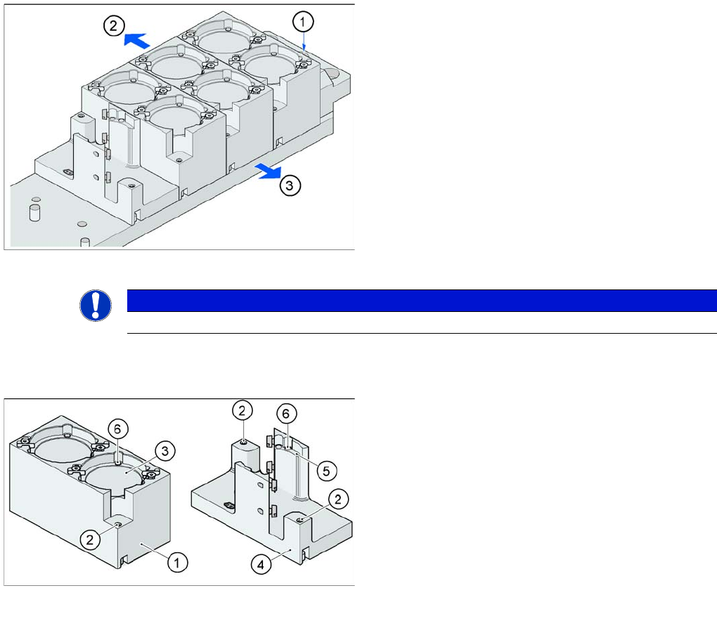
Fitting the magazine (X/D3 machine)
The nozzle changer together with the empty tape duct is
fixed on the component docking unit. The magazines are
seated on a common support. They are centered with two
parallel pins and fixed in place with two countersunk
screws.
Legend
1. Nozzle changer marking hole
2. Operator side (changeover table side)
3. Arrow pointing toward the PCB conveyor
Align the nozzle changer so that the marking hole (item
1) is on the left, as viewed by the operator (at the
changeover table side).
NOTICE
On X machines with MTC a special adapter for the TwinHead nozzle changer is required.
Magazine for standard and special nozzles (HF/X/D3
machine shown here as example)
Legend
1. Standard magazine
2. Positioning fiducial
3. Nozzle garage
4. Magazine for special nozzles
5. Nozzle garage
6. Balls for lifting the nozzles
TwinHead
Nozzle Changer for TwinHead Nozzle changer
Student Guide SIPLACE X-Serie and X4I SW70x (AL2) 346
Position of the nozzle in the magazines
Nozzle Changer for TwinHead
9.5.3 Nozzle Changer for TwinHead
All SIPLACE machines configured with a TwinHead are delivered with a nozzle changer by default. This
nozzle changer can accommodate up to 12 nozzle magazines. There are two types of magazine
available: standard magazines and magazines for special nozzles or grippers. Depending on the
machine type the nozzle changer can be freely configured with magazines. The nozzle changer consists
of a standard module with 3 nozzle garages, for two nozzles each (standard nozzles) and one nozzle
garage for a special nozzle. This configuration can be extended as shown in the diagram below.
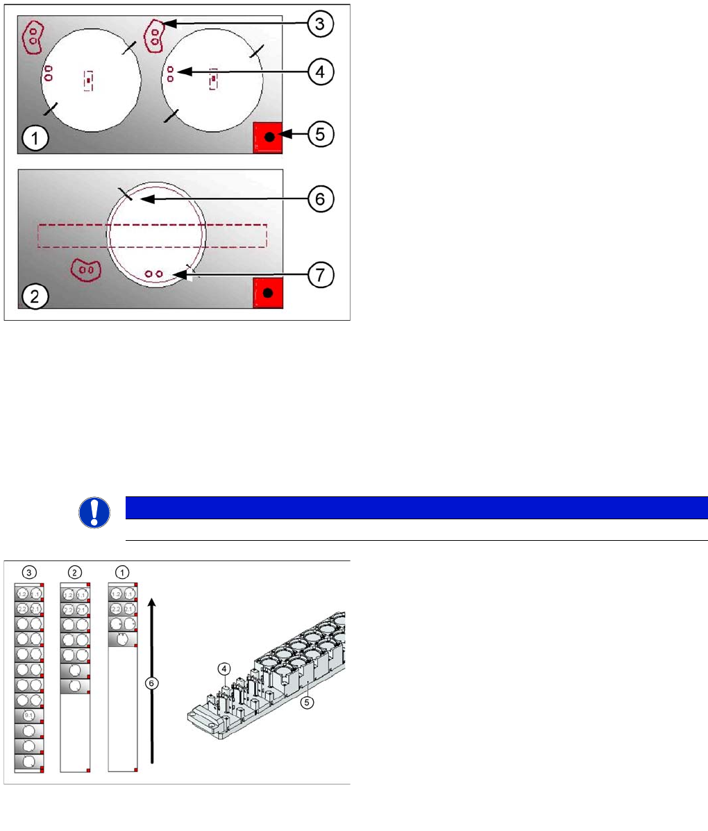
Legend
1. Double magazine for standard nozzles (pickup angle
SW 505 = 184°)
2. Magazine for special nozzles or grippers (pickup
angle SW 505 = 275°)
3. Index pins for correct positioning of nozzles in
magazine
4. Position of nozzle with the holes for the index pins.
5. Calibration fiducial for determining the magazine
position
6. Nozzle centering pins
7. The magazines for the special nozzles are turned by
90° degrees.
NOTICE
The magazines for standard and special nozzles are freely configurable with SW 505 or higher.
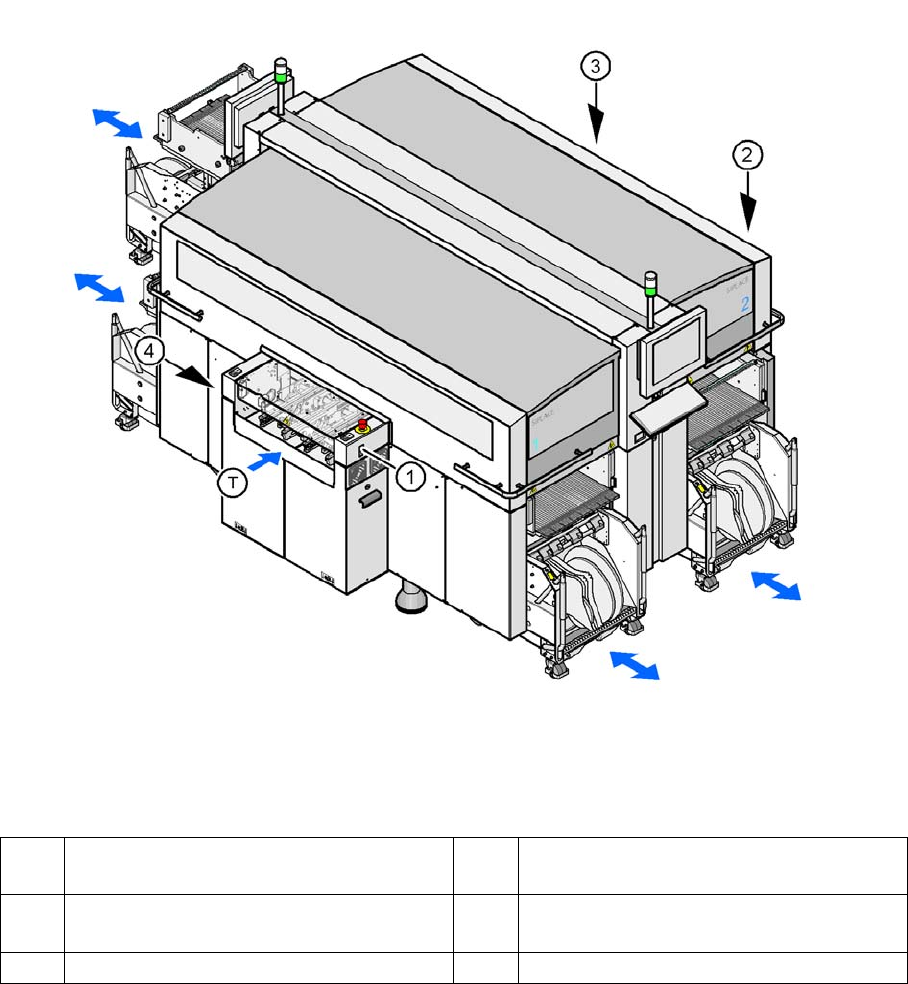
Example for a nozzle changer configuration for a
TwinHead
Legend
1. Standard nozzle changer
2. Extended Nozzle changer
3. Complete Nozzle changer
4. Magazine for 1 special nozzle
5. Magazine for 2 standard nozzles
6. Transport direction
Component Handling
Changeover Table Overview
347 Student Guide SIPLACE X-Serie and X4I SW70x (AL2)
Component Handling
10 Component Handling
Changeover Table
10.1 Changeover Table
Overview
10.1.1 Overview
This chapter describes the preparation of components with the changeover tables, the corresponding
docking unit and the pneumatic cutter.
Up to four moveable changeover tables can be docked onto the X machine. The changeover tables are
automatically connected to and disconnected from the docking unit (mechanically and electrically) by
pressing a button. MTC2s can also be used with all X series machines (except X4I).
Shows the buttons for docking and undocking the COT‘s
Legend
Changeover Table (X Table)
10.1.1.1 Changeover Table (X Table)
The changeover table and the docking unit form a component supply unit.
1 Button for docking and undocking the
component trolley to location 1
3 Button for docking and undocking the
component trolley to location 3
2 Button for docking and undocking the
component trolley to location 2
4 Button for docking and undocking the
component trolley to location 4
T Direction of board transport