00194614-08 Trainingsdoku. SG X-Serie_X4i SW70x (AL2)_EN.pdf - 第454页
MTC2 Modules of the controller Construction and mode of operation Student Guide SIPLACE X-Serie and X4I SW70x (AL2) 454 – X01 feed-in – X02 24 V voltage supply for sensors/ac tuators – X03 emergency stop circuit – X04 se…
MTC2
Construction and mode of operation Modules of the controller
453 Student Guide SIPLACE X-Serie and X4I SW70x (AL2)
▪ Displaying operating statuses and error statuses via LEDs
Two RS232 interfaces (maximum transfer rate: 115.2 kBaud/s)
▪ COM 1: Test interface for debugging service
▪ COM 2: Free
Two CAN bus interfaces (maximum transfer rate: 1 MBaud/s)
▪ CAN1: Communication with the SIPLACE station
▪ CAN2: Control of the 4 Masterdrives
Power supply: 24 VDC
▪ Power consumption: 500 mA
24 inputs via a 37-pole Sub-D connector for the sensors
8 inputs via a 15-pole Sub-D connector for the actuators;
▪ The outputs are short-circuit proof;
▪ Current per output: 0.7 A, briefly up to 2.5A
Masterd rives
13.2.5.2 Masterdrives
The Masterdrives are controlled via the internal CAN bus system between microcontroller and
masterdrive.
▪ Controlling the holding brakes for the lifting axes
▪ Controlling the braking resistors of the lifting axes
▪ Controlling the permanently excited synchronous motors of the lifting and feed axes
▪ Evaluating the resolver
24V power supply
13.2.5.3 24V power supply
The 24V power supply supplies:
▪ The C167 controller board
▪ The logic circuitry of the Masterdrives
▪ The sensors and the actuators
Electron ics board
13.2.5.4 Electronics board
Electronics board with the following components:
▪ Main switch: S01
▪ EMERGENCY STOP button: S15
▪ Automatic circuit breakers:
– F00 main fuse
– F01 24 V sensors 1
– F02 24 V sensors 2, master drive control voltage
▪ Motor protection swtich: Q01 Masterdrives
▪ Contactors:
– K01.1 master drive lifting axis tower 1
– K01.2 master drive feed axis tower 1
– K02.1 master drive lifting axis tower 2
– K02.2 master drive feed axis tower 2
▪ Optocouplers:
– U09 brake tower 1
– U06 brake tower 2
▪ Terminal strips:
MTC2
Modules of the controller Construction and mode of operation
Student Guide SIPLACE X-Serie and X4I SW70x (AL2) 454
– X01 feed-in
– X02 24 V voltage supply for sensors/actuators
– X03 emergency stop circuit
– X04 sensors/actuators tower 1
– X05 sensors/actuators tower 2
– X06 sensors/actuators
Mounting pl ate
13.2.5.5 Mounting plate
A mounting plate with the following components:
▪ Combination circuit breakers: K03 - K05
▪ Braking resistor: R01
▪ Braking resistor: R02
▪ Power supply, 24 V DC: T01
▪ Line filter: Z01
▪ Discharge reactor (Is this part missing in your MTC please order the retrofitting kit 03016518-01, that
for your own safety.)
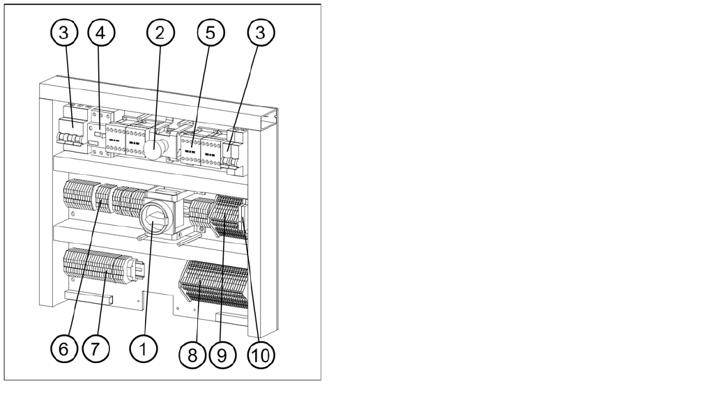
Electronics board and mounting plate 1
Legend
1. Main switch
2. EMERGENCY STOP button
3. Automatic circuit breakers
4. Motor Circuit Breaker
5. Contactors
6. Grounding terminals
7. Through terminals
8. Initiator LED terminals
9. Actuator LED terminals
10. Optocouplers
MTC2
Construction and mode of operation Modules of the controller
455 Student Guide SIPLACE X-Serie and X4I SW70x (AL2)
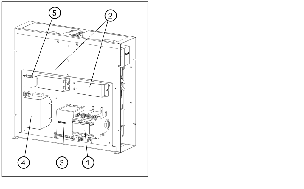
Electronics board and mounting plate 2
Legend
1 Combination circuit breakers
2 Braking resistors
3 Power supply
4 Line filters
5 Discharge reactor