00194614-08 Trainingsdoku. SG X-Serie_X4i SW70x (AL2)_EN.pdf - 第109页
Communication and Control CAN Bus CAN I/O Module (SLIO) SIPLACE X 109 Student Guide SIPLACE X-Serie and X4I SW70x (AL2) I/O Module for Mai n Distribu tor (Outpu ts) 4.3.10.3 I/O Module for Main Distributor (Outputs) nc= …
Communication and Control
CAN I/O Module (SLIO) SIPLACE X CAN Bus
Student Guide SIPLACE X-Serie and X4I SW70x (AL2) 108
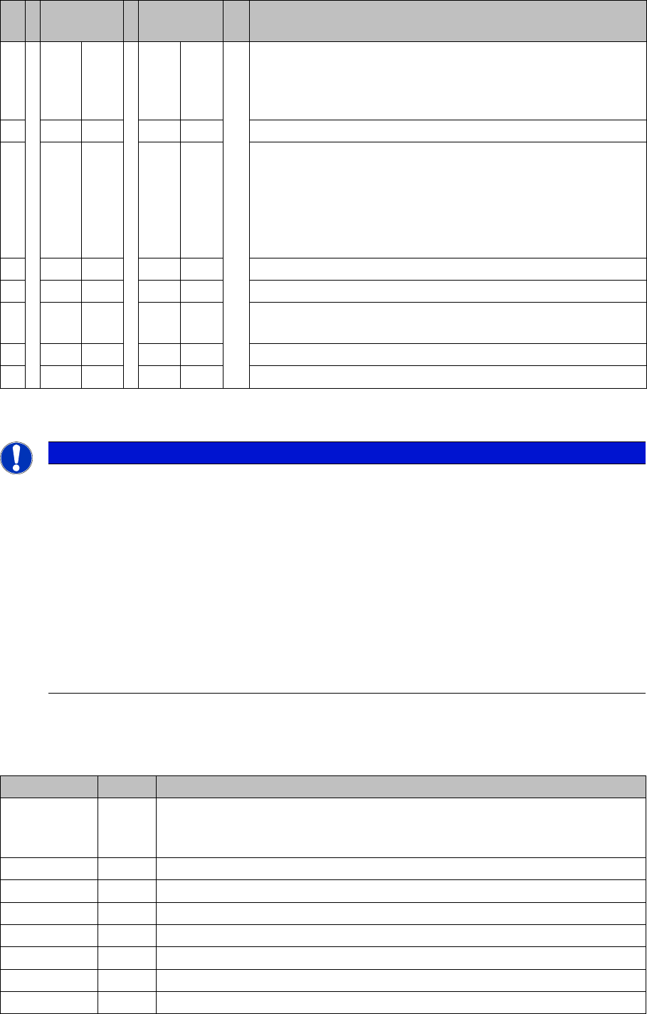
Description of I/O Modul e
Description of I/O Module
I/O Module, Main Dist ributor (Inputs) [new from B323: 03046225-01]
4.3.10.2 I/O Module, Main Distributor (Inputs) [new from B323: 03046225-01]
nc = not connected (reserve)
S Main
distributor
Subdistribut
or
Comments
1 OFF OFF Gateway ON/OFF:
This switch opens the SUB CAN bus to address the tables and
cutters on the D1, D2 and D4 machines or the WPC on the X2
and X 3 from SW 605.
2 OFF OFF SW platform: ON: HF/HF3, OFF: D3, X series X4I
3 OFF OFF Baudrate - ON = 1 MBit/s, OFF = 500 KBit/s:
This switch is only queried if switch S1 is set to ON.
D1, D2, X2, X3 with WPC (SW 605): ON
D4: OFF
X2, X3 without WPC, X4, X4I: The switch can be set to OFF
here as switch S1 is also set to OFF.
4 OFF ON Location: ON: Subdistributor, OFF: Main distributor
5 OFF OFF Not in use
6 OFF OFF OFF: The connected Interface 1-Wire CAT5 board is active if
the switches on it are set to V2 and MA.
7 OFF OFF HW reset for 1-Wire
8 OFF OFF OFF: X series, X4I, D4, ON: D1/D2
NOTICE
Description of I/O Module
The I/O assemblies of version 02 and 03 differ in that the "Interface 1-Wire CAT5" board is
integrated into version 03.
This means that this integrated "Interface 1-Wire CAT5" board can only be used for HF/HF3
machines.
X machines have the "Interface 1-Wire CAT5" connected as an additional module, due to the
CAT5 connection. By setting the switch on the interface to MA and Version 02 the integrated
interface is switched off and the machine uses the additionally connected interface.
► The same I/O assembly is used for D series machines but with a different eSW. This results
in other DIP switch settings (see table above). The additionally connected interface is used
to address the components and cutters via a sub CAN bus.
Terminals I / O Description / Note
X3_1 Di0 M_NotAusSchleife1ok or M_Security Loop ("high" if all safety loops are closed
(protective hoods, emergency STOP buttons, component flaps, changeover
tables).
X3_2 Di1 nc
X3_3 Di2 nc
X3_4 Di3 M_BeKlappe ("high" if one or more flaps open.)
X3_5 Di4 nc
X3_6 Di5 nc
X3_7 Di6 nc
X3_8 Di7 nc

Communication and Control
CAN Bus CAN I/O Module (SLIO) SIPLACE X
109 Student Guide SIPLACE X-Serie and X4I SW70x (AL2)
I/O Module for Main Distributor (Outputs)
4.3.10.3 I/O Module for Main Distributor (Outputs)
nc= not connected (Reserve)
X4_1 Di8 nc
X4_2 Di9 M_Bereit/Message changes from "low" to "high" if the SSK (K6) triggers, only
possible if "Steuerung_EIN" is on (control on).
X4_3 Di10 M_Vakuum OK
X4_4 Di11 M_PortalCrash1 "low" signal that gantries 1 and 4 are too close,"high" signal
is normal status
X4_5 Di12 nc
X4_6 Di13 M_ServoEnable1 or Control ON/ "high" signal - intermediate circuit voltage for
X/Y servo on axis unit 1 switched through. (K4 message)
X4_7 Di14 nc
X4_8 Di15 M_Drucksensor RV/TwinHead "high" signal if compressed air level reached.
X5_1 Di16 24 V M_NotAus-Schleife 2 OK
X5_2 Di17 M_Haube2 "high" signal if cover 2 is closed
X5_3 Di18 M_BE-Tisch2 "high" signal if changeover table 2 is docked
X5_4 Di19 M_HaubeLP-Ausgabe "high"signal if the cover above the PCB output is
closed.
X5_5 Di20 M_NotAusTasteLP-Ausgabe "high" signal if the emergency STOP button is
unlocked.
X5_6 Di21 M_Haube3 "high" signal if cover 3 is closed.
X5_7 Di22 M_BE-Tisch3 "high" signal if changeover table 3 is docked
X5_8 Di23 nc
X6_1 nc
X6_2 nc
X6_3 GND
X6_4 nc
X6_5 nc
X6_6 nc
X6_7 nc
X6_8 nc
Terminals I / O Description / Note

Communication and Control
CAN I/O Module (SLIO) SIPLACE X CAN Bus
Student Guide SIPLACE X-Serie and X4I SW70x (AL2) 110
Terminals I / O Description / Note
X7_1 Do0 nc
X7_2 Do1 St_Ein or software release
When a "high" signal is permanently supplied to this port (24 V), the
SIPLACE machine can be put into operation. The message M_Ready
changes from "low" to "high" (IO1/Di9), if relay K5 has latched (24 V).
The emergency stop loop1 and the start buttons to the protective
contactor combination -SSK (K6). Once all 6 hoods are closed, all 4
component flaps are closed, the two emergency STOP buttons
unlocked and all component trolleys docked into place, the protective
contactor combination can be activated with one of the start buttons.
The SSK switches:
1. The contactors K2, K3 and K4 are switched on and the intermediate
circuit voltage (somewhat delayed) is supplied to the X, Y and star
servo axis boards.
2. The operating voltage,
3. The compressed air (valve) at the tape cutters.
4. Two safety loops for the MTCs.
5. The power supply for the PCB conveyor motors ON.
X7_3 Do2 nc
X7_4 Do3 St_DruckluftRV/Twin pneumatic OFF (a "low" signal opens the
compressed air main valve. A "high" signal closes this.
X7_5 Do4 St_BauteilZähler/Each "high" pulse increases the counter by one.
X7_6 Do5 nc
X7_7 Do6 nc
X7_8 Do7 nc
X8_1 Do8 nc
X8_2 Do9 nc
X8_3 Do10 nc
X8_4 Do11 nc
X8_5 Do12 St_GrüneLampe1/The right-hand green light from the fault indicator
shines if a "high" signal is present at the port output. Definition: Flashed
when no PCB board in the right conveyor lane.
X8_6 Do13 St_WeisseLampe1/The right-hand white light of the fault indicator lamp
shines if a "high" signal is present at the port output. Definition: Fault
on a feeder on location 1 or 2.
X8_7 Do14 St_WeisseLampe2/The left-hand white light of the fault indicator
shines if a "high" signal is present at the port output. Definition: Fault
on a feeder on location 3 or 4.
X8_8 Do15 St_GrüneLampe2/The left-hand green light from the fault indicator
shines if a "high" signal is present at the port output. Definition: Flashed
when no PCB board in the left conveyor lane.
X9_1 24 V
X9_2 24 V
X9_3 24 V
X9_4 24 V
X9_5 GND
X9_6 GND
X9_7 GND
X9_8 GND