00194614-08 Trainingsdoku. SG X-Serie_X4i SW70x (AL2)_EN.pdf - 第107页
Communication and Control CAN Bus CAN I/O Module (SLIO) SIPLACE X 107 Student Guide SIPLACE X-Serie and X4I SW70x (AL2) CAN I/O Modu le (SLIO) SIPLA CE X 4.3.10 CAN I/O Module (SLIO) SIPLACE X SIPLACE X machines use 2 CA…
Communication and Control
X Feeder - Communication CAN Bus
Student Guide SIPLACE X-Serie and X4I SW70x (AL2) 106
Data Transfe r
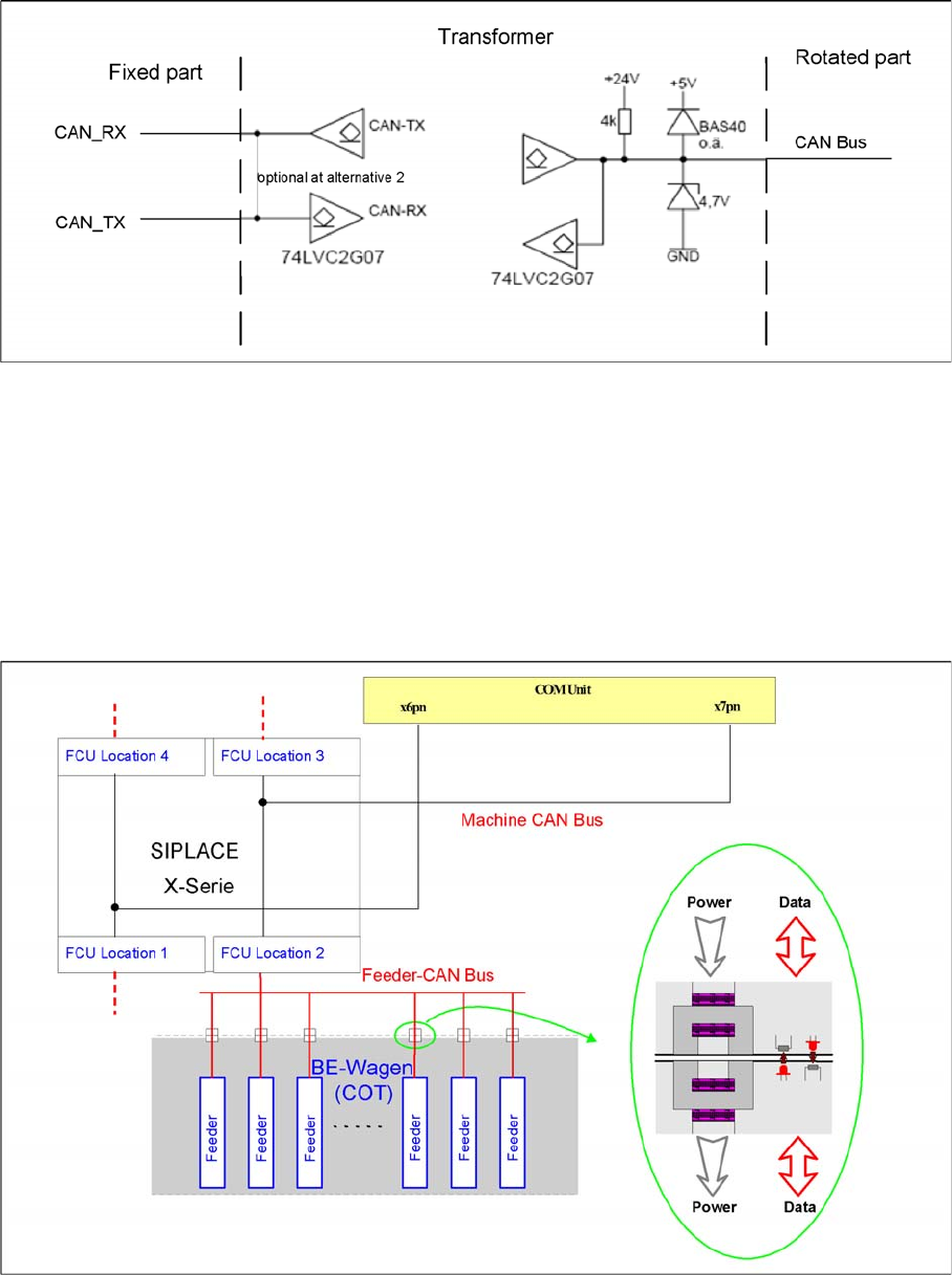
4.3.8.4 Data Transfer
▪ The communication with the DP drives (CAN bus) is contactless via a transmitter unit (on the back
cover of the CPP head) and a receiver unit (on the valve terminal).
▪ This communication is via 2 channels, whereby channel 1 is responsible for supplying data to the
DP drives and channel 2 is responsible for communication to the Z down light barrier of the axis card
(HCU).
▪ The head CAN bus is – in this case – not used as a differential CAN bus with the CAN_L and CAN_H
signals but as a 1 wire CAN on the rotor.
X Feeder - Comm unicatio n
4.3.9 X Feeder - Communication
Communication X feeder
The communication between the Feeder Control Unit (FCU) and each X feeder is carried out via a CAN
bus. This CAN bus is only responsible for the communication between the FCU and the feeders and is
controlled by the machine CAN bus.
The data and power supply from the FCU to each feeder is contactless.
Communication and Control
CAN Bus CAN I/O Module (SLIO) SIPLACE X
107 Student Guide SIPLACE X-Serie and X4I SW70x (AL2)
CAN I/O Modu le (SLIO) SIPLA CE X
4.3.10 CAN I/O Module (SLIO) SIPLACE X
SIPLACE X machines use 2 CAN I/O modules. Both modules are absolutely identical and are located in
sectors 2 (main distributor) and 4 (subdistributor). The introduction of the one wire bus system means
that there is now an additional board plugged into the I/O module (Interface 1-Wire CAT5).
Product characteristics:
▪ Micro controller with integrated CAN controller
▪ Data memory
▪ Program memory (flash)
▪ CAN interface with 9 pin connector and address alignment
▪ 16 digital Output 24 V with status LED
▪ 24 digital Input 24 V with status LED
▪ Download interface
▪ Power supply 24V
The 8 digital inputs can be logically linked with the help of a FPGA (freely programmable gate array).
The FPGA is used for incoming security messages.
Example: Subdistributor
Legend
The jumper on the rear side activates the RS232 interface for service purposes.
DIP Switch on Main and Subdistributor (for Version -03)
4.3.10.1 DIP Switch on Main and Subdistributor (for Version -03)
DIP switch on CAN I/O module (X-series from Ma No. B-326, X4I).
Applies for main distributors [03046225-xx] and subdistributors [03046226-xx].
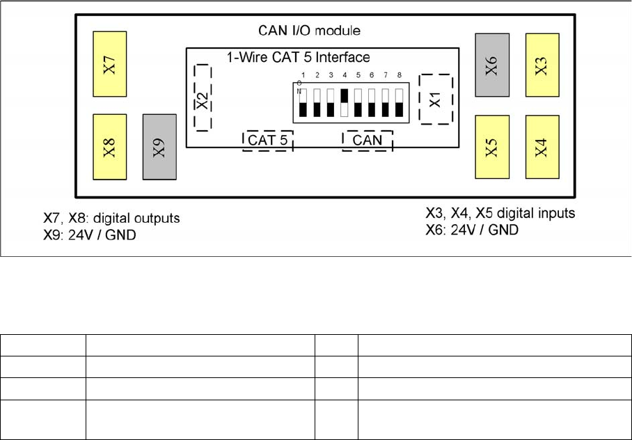
X1 CAN Bus Interface to I/O module X2 RS232 interface
X3, X4, X5 Digital inputs 24V X6 24 V / GND
X7, X8 Digital outputs 24V X9 24 V / GND
CAT5 Interface 1-Wire connector CAT5
cable
CAN CAN bus connector
Communication and Control
CAN I/O Module (SLIO) SIPLACE X CAN Bus
Student Guide SIPLACE X-Serie and X4I SW70x (AL2) 108
Description of I/O Modul e
Description of I/O Module
I/O Module, Main Dist ributor (Inputs) [new from B323: 03046225-01]
4.3.10.2 I/O Module, Main Distributor (Inputs) [new from B323: 03046225-01]
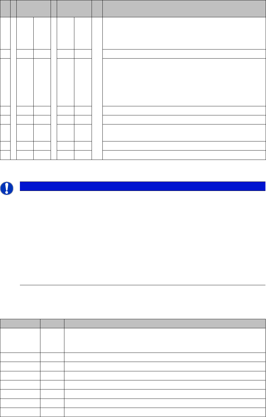
nc = not connected (reserve)
S Main
distributor
Subdistribut
or
Comments
1 OFF OFF Gateway ON/OFF:
This switch opens the SUB CAN bus to address the tables and
cutters on the D1, D2 and D4 machines or the WPC on the X2
and X 3 from SW 605.
2 OFF OFF SW platform: ON: HF/HF3, OFF: D3, X series X4I
3 OFF OFF Baudrate - ON = 1 MBit/s, OFF = 500 KBit/s:
This switch is only queried if switch S1 is set to ON.
D1, D2, X2, X3 with WPC (SW 605): ON
D4: OFF
X2, X3 without WPC, X4, X4I: The switch can be set to OFF
here as switch S1 is also set to OFF.
4 OFF ON Location: ON: Subdistributor, OFF: Main distributor
5 OFF OFF Not in use
6 OFF OFF OFF: The connected Interface 1-Wire CAT5 board is active if
the switches on it are set to V2 and MA.
7 OFF OFF HW reset for 1-Wire
8 OFF OFF OFF: X series, X4I, D4, ON: D1/D2
NOTICE
Description of I/O Module
The I/O assemblies of version 02 and 03 differ in that the "Interface 1-Wire CAT5" board is
integrated into version 03.
This means that this integrated "Interface 1-Wire CAT5" board can only be used for HF/HF3
machines.
X machines have the "Interface 1-Wire CAT5" connected as an additional module, due to the
CAT5 connection. By setting the switch on the interface to MA and Version 02 the integrated
interface is switched off and the machine uses the additionally connected interface.
► The same I/O assembly is used for D series machines but with a different eSW. This results
in other DIP switch settings (see table above). The additionally connected interface is used
to address the components and cutters via a sub CAN bus.
Terminals I / O Description / Note
X3_1 Di0 M_NotAusSchleife1ok or M_Security Loop ("high" if all safety loops are closed
(protective hoods, emergency STOP buttons, component flaps, changeover
tables).
X3_2 Di1 nc
X3_3 Di2 nc
X3_4 Di3 M_BeKlappe ("high" if one or more flaps open.)
X3_5 Di4 nc
X3_6 Di5 nc
X3_7 Di6 nc
X3_8 Di7 nc