00194614-08 Trainingsdoku. SG X-Serie_X4i SW70x (AL2)_EN.pdf - 第460页
MTC2 General Work Before Starting th e MTC2 C onstruction and mode of o peration Student Guide SIPLACE X-Serie and X4I SW70x (AL2) 460 General Wo rk Before Starting the MTC2 13.2.7 General Work Bef ore Starting the MTC2 …
MTC2
Construction and mode of operation Installation of MTC2
459 Student Guide SIPLACE X-Serie and X4I SW70x (AL2)
Installati on of MTC2
13.2.6 Installation of MTC2
In the installation manual the modification is described for a HF machine. The cables aren't available to
newer HF/HF3 and at the SIPLACE X machines at the side of the machine. All cables which go to the
docking frame are in the machine frame and must be attached according to the cable name.
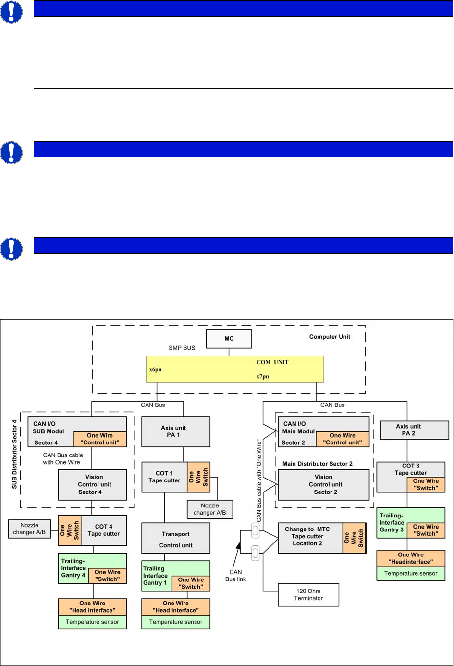
The CAN Bus bridge is needed either at location 2 or 4, depending on the location at which you install
the MTC2.
Additional CAN Bus bridge for MTC2, if one wire bus has not been realized with a CAT5 cable
NOTICE
If you change the changeover table to an MTC2 at location 2 and/or 4 of a SIPLACE HF/HF3
or SIPLACE X machine, you will also need to change the whole docking unit (time needed
approx. 1 hour).
► Installation manual: Conversion of component trolley to MTC2 (00193897-01.pdf / German,
English)
NOTICE
The HF machines with the series number A 001 and the SIPLACE X machines are equipped
with a "One Wire bus" which is integrated in the Can bus. If you install an MTC2 on these
machines, you must bridge the CAN Bus cable before the docking frame of the MTC.
Reason: The wiring in the docking frame can transmit the CAN Bus signals but not the one wire
signals.
NOTICE
The CAN Bus link is necessary, if the one wire cable integrated into the CAN Bus cable. When
the One Wire Bus installed with CAT5 cable, the CAN Bus link is not necessary.
MTC2
General Work Before Starting the MTC2 Construction and mode of operation
Student Guide SIPLACE X-Serie and X4I SW70x (AL2) 460
General Work Before Starting the MTC2
13.2.7 General Work Before Starting the MTC2
▪ Setting the basic height
▪ Installing the safety cover for the lifting axis
▪ Docking
▪ Undocking
Placement Functions
13.2.8 Placement Functions
Main View wi th MTC2
13.2.8.1 Main View with MTC2
MTC2 - Pla cement Fun ctions
13.2.8.2 MTC2 - Placement Functions
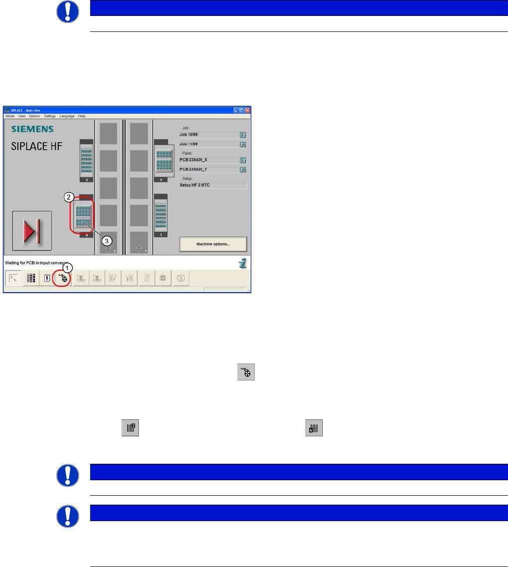
In the toolbar of the main view, select the icon for the menu function Feeders .
The user interface will switch to the Empty tracks view, when the Feeders menu is called up for the
first time, after the station computer software has been started.
Select the icon for the MTC2 at location 2 or the icon for the MTC2 at location 4.
The Matrix-tray changer view will be shown for the selected location.
See also
13.2.8.3 "Matrix-tray changer" view (Example: location 2) [ ➙ 461]
13.2.8.1 Main View with MTC2 [ ➙ 460]
NOTICE
see User manual 00193634-01_de.pdf / 00193635-01_eng.pdf.
Main view of the SIPLACE HF with MTC2 at locations
and 4
Legend
1. "Feeders" view
2. MTC2 at location 4
3. MTC 2 setup, towers 1 and 2
NOTICE
The icon for the MTC2 at the relevant location is only displayed if an MTC2 is available there.
NOTICE
If a setup is available for an MTC2 , it will be displayed in the main view of the diagram for the
relevant MTC2 .
Select this to open the Matrix-tray changer view for the MTC2 at the selected location.
MTC2
Construction and mode of operation Placement Functions
461 Student Guide SIPLACE X-Serie and X4I SW70x (AL2)
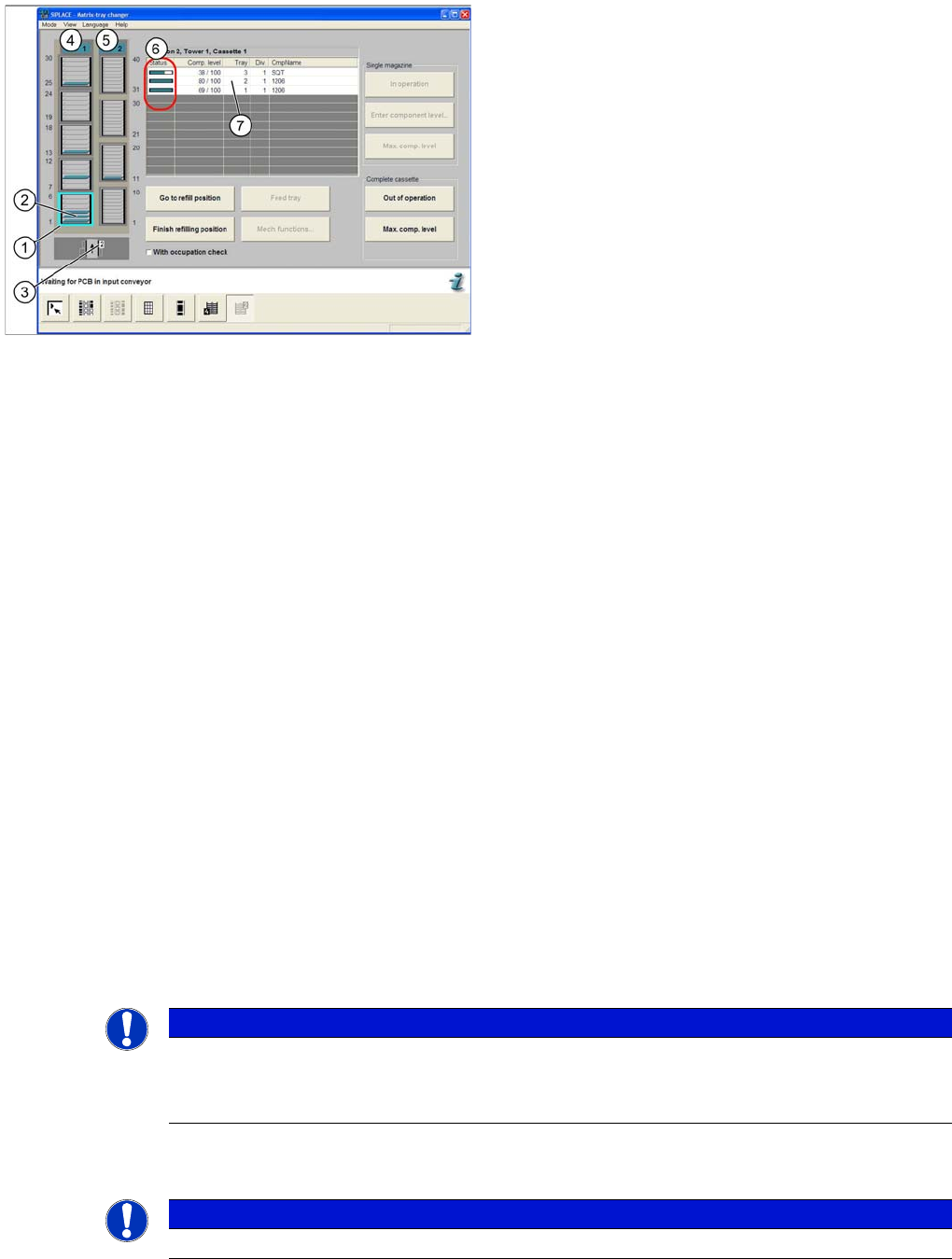
"Matrix-tra y changer" v iew (Examp le: locatio n 2)
13.2.8.3 "Matrix-tray changer" view (Example: location 2)
Terms used for the occupancy of a cassette
13.2.8.4 Terms used for the occupancy of a cassette
▪ Status
Status display for the current component level
▪ Component level
Current and maximum component level (is updated approximately every 30 seconds during
placement).
▪ Level
Number of the level
(a cassette is subdivided into 6 or 10 levels)
▪ Division
Number of the component division in the waffle pack tray
(a maximum of 150 divisions can be defined.)
▪ Component name
Name of the corresponding component in the waffle pack tray
Functio ns in the "Matrix-tray cha nger" vi ew
13.2.8.5 Functions in the "Matrix-tray changer" view
▪ Button Go to refill position
The MTC2 moves the tower to the refill position of the selected cassette.
The status indicator of the active tower turns yellow.
▪ Button Finish refilling position
Refilling is completed and placement with the selected cassette continues.
The status indicator of the active tower turns green.
▪ Button Prepare level
The selected tray will be moved out to the transfer position.
"Matrix-tray changer" view
Legend
1. Selected cassette
2. Levels in the cassette
3. View of the location
4. Status indicator for tower 1
5. Status indicator for tower 2
6. Display of component level and occupancy of the
selected cassette
7. Selected list entry for a level
NOTICE
If the checkbox With occupation check is selected, the setup of the refilled cassette will
be checked by moving to every level of the selected cassette.
The result of the check is displayed in a separate dialog box.
NOTICE
If there is already a waffle pack tray in the transfer position, it is first moved back to the tower.