00194614-08 Trainingsdoku. SG X-Serie_X4i SW70x (AL2)_EN.pdf - 第181页
Energy and Compressed Air Supply Pneumatic System Compressed Air Supply CPP 181 Student Guide SIPLACE X-Serie and X4I SW70x (AL2) Compresse d Air Supply CPP 5.3.12 Compressed Air Supply CPP Compresse d Air Distr ibution …
Energy and Compressed Air Supply
Bulk Case System and Nozzle Changer Pneumatic System
Student Guide SIPLACE X-Serie and X4I SW70x (AL2) 180
Bulk Case System and Nozzle Changer
5.3.10 Bulk Case System and Nozzle Changer
Another adjustable regulator is used to reduce the 5.0 bar to 2.5 +0.5 bar. This air supply is used for the
bulk case and for the nozzle changer at the C&P 6/12 head.
Compressed A ir Supply to the C&P20A
5.3.11 Compressed Air Supply to the C&P20A
The 4.8 bar air supply to the C&P20A is needed for the following functions:
▪ Vacuum supply in the holding circuit
▪ Vacuum and air blast supply for the placement circuit (pressure control valve)
▪ Cooling facility for the X axis motor.
Z Axis Safety Mode
5.3.11.1 Z Axis Safety Mode
Legend
1. Rear view of the pneumatic distributor
Input:
- 7 fold pneumatic hose (PK 6)
- 2 fold pneumatic hose
- Optional vacuum pump (PK 10)
2. Front view of the pneumatic distributor
Output:
C&P20A Head
3. Pressure Control Valve
4. Return cylinder
5. Hold circuit
NOTICE
With the introduction of the "Fast head exchange", the retract unit and the pressure control
valve are supplied via a PK6 connection from the pneumatic distributor.
Z axis retract unit
Legend
1. Retract unit on the C&P20A head
Another use of the 4.8 bar compressed air is for the Z axis
safety mode. As long as the machine is in normal mode,
the Z axis can move freely within its travel range. In the
case of power cuts or when the machine is switched off,
a safety mode is needed since the weight of the Z axis
causes it to fall down and it could be damaged when the
gantry is moved. With the help of the retract unit, the Z
axis can be moved to a safe position in just a few ms. In
the event of a fault, like a power cut, the power fail mode
is also activated, which powers the Z axis for about 200
ms seconds with the aid of a capacitor, located in the
main power supply. This ensures that the Z axis moves
up with the power provided and with additional help from
the return spring.
Energy and Compressed Air Supply
Pneumatic System Compressed Air Supply CPP
181 Student Guide SIPLACE X-Serie and X4I SW70x (AL2)
Compresse d Air Supply CPP
5.3.12 Compressed Air Supply CPP
Compresse d Air Distr ibution Tw in Head
5.3.13 Compressed Air Distribution Twin Head
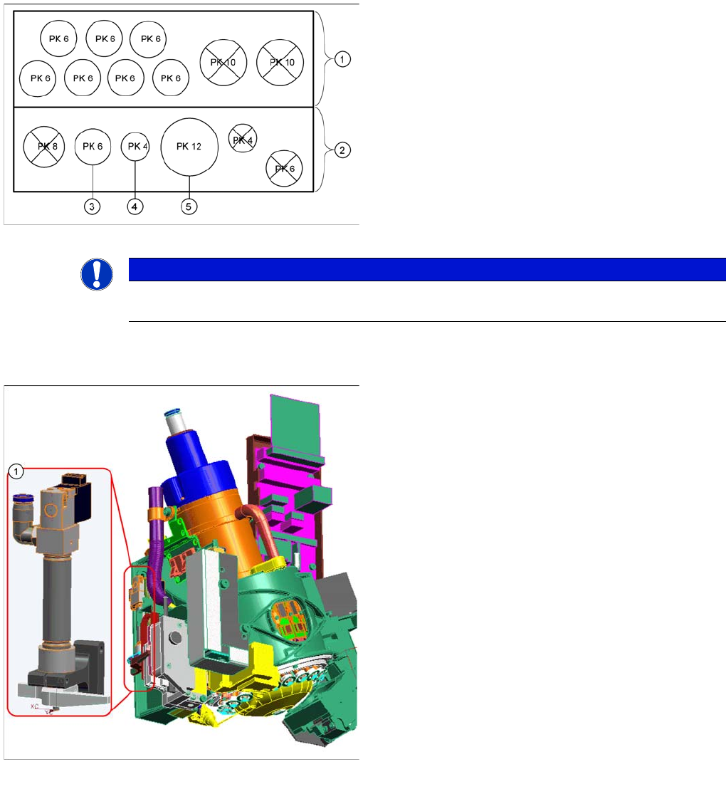
Legend
1. Rear view of the pneumatic distributor
Input:
- 7 fold pneumatic hose (PK 6)
- 2 fold pneumatic hose
- Optional vacuum pump (PK 10)
2. Front view of the pneumatic distributor
Output:
- CPP head
3. Hold circuit
4. Return cylinder
5. Pressure control valve
NOTICE
With the introduction of the "Fast head exchange", the retract unit and the pressure control
valve are supplied via a PK6 connection from the pneumatic distributor.
Pneumatic distributor for trailing cable CFK06/
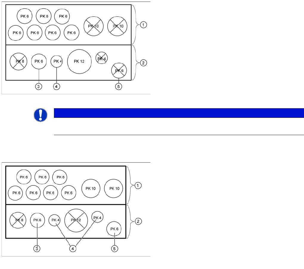
Legend
1. Rear view of the pneumatic distributor
Input:
- 7 fold pneumatic hose (PK6)
- 2 fold pneumatic hose (PK10)
2. Front view of the pneumatic distributor
Output:
- Twin Head
3. Pressure control valve segment 1
4. Return cylinder segment 1 and 2
5. Pressure control valve segment 2
Energy and Compressed Air Supply
Cooling the X Axis Motors Pneumatic System
Student Guide SIPLACE X-Serie and X4I SW70x (AL2) 182
Cooling the X Axis Motors
5.3.14 Cooling the X Axis Motors
Cooling the Y Axis Motors fo r Placement Are a 1/2
5.3.15 Cooling the Y Axis Motors for Placement Area 1/2
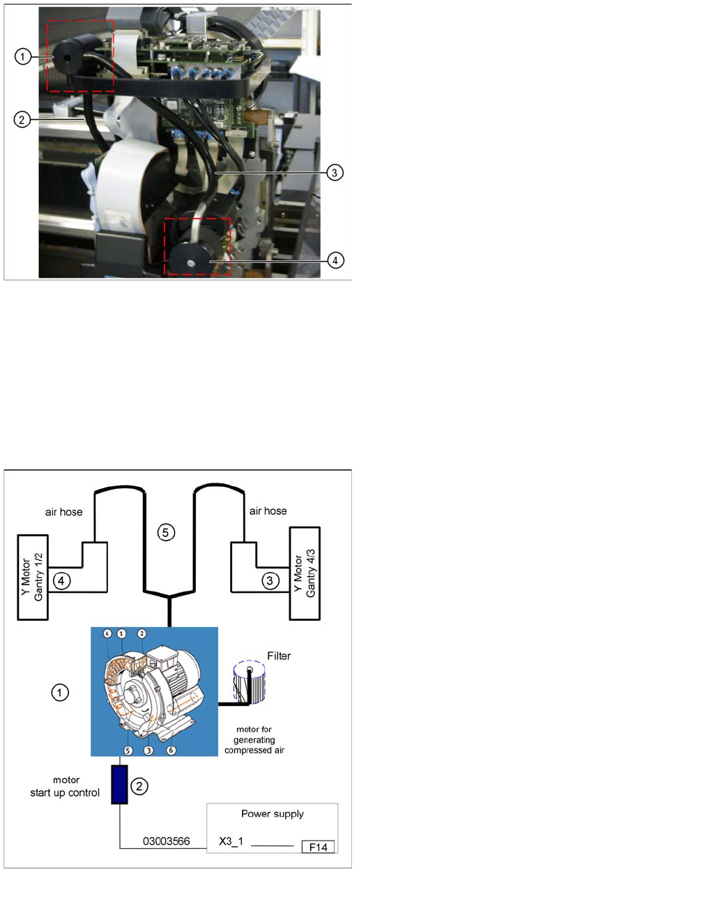
To cool the Y axis motors, an additional pneumatic system is integrated, which sucks the air from the
environment, compresses it in a compressor and conducts its through a hose system to each of the Y
axis motors.
The motor coil temperature is monitored. If this exceeds 110°C, a message will appear on your screen.
This simple cooling system is installed to ensure that the Y axis does not overheat.
Cooling system X axis motor
The exhaust air from the vacuum generator (pressure
control valve) of the C&P head is used to cool the X axis
motors.
Legend
1. Air distributor
2. Air tube for cooling the X axis
3. Hose via the distributor to the pneumatic unit
4. Silencer
Cooling system Y axis motor
Legend:
1. Compressor, located in main unit
2. Startup control for the compressor
3. Y axis motor gantry 4/3
4. Y axis motor gantry 1/2
5. air hose for air supply used for cooling the linear
motor