00194614-08 Trainingsdoku. SG X-Serie_X4i SW70x (AL2)_EN.pdf - 第356页
Component Handling X Feeder Parts (Front View) X Feeder Student Guide SIPLACE X-Serie and X4I SW70x (AL2) 356 X Feede r Par ts (Fron t View) 10.2.2 X Feeder Parts (Front View) X feeder parts (front view) Legend X Splice …
Component Handling
X Feeder General
355 Student Guide SIPLACE X-Serie and X4I SW70x (AL2)
X Feeder
10.2 X Feeder
General
10.2.1 General
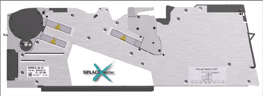
X feeder - basic view
Performance :
Increased demand for speed at C&P20A head (Communication, dynamics 40ms for 4mm), Feeder
should not limit placement (communication, transport)
Precision :
Designed for smallest components currently on the market
Reliability:
Reliable drive system, "Closed loop" drive regulation, new mechanical interface, new electrical interface,
brushless DC motors, optimized gear
Flexibility :
Different pitches adjustable, "Hot swapping" possible, upgrade per firmware download possible with
station software, adaptable for "problematic tapes", free step width, variable speed profiles
Usability :
Single track feeder, Tape loading, Interface to operator, Integrated Splice recognition (optional), Able to
handle sticky tapes (optional PSA kit (pressure sensitive adhesive)), no connectors and cables, operator
panel
Intelligence :
Unique feeder- ID, Management data (cycles, power up hours, errors,...), Object data are stored in set-
up control data base
Robustness :
No "on mechanical end stops" --> controlled movement of the transport
Component Handling
X Feeder Parts (Front View) X Feeder
Student Guide SIPLACE X-Serie and X4I SW70x (AL2) 356
X Feeder Parts (Front View)
10.2.2 X Feeder Parts (Front View)
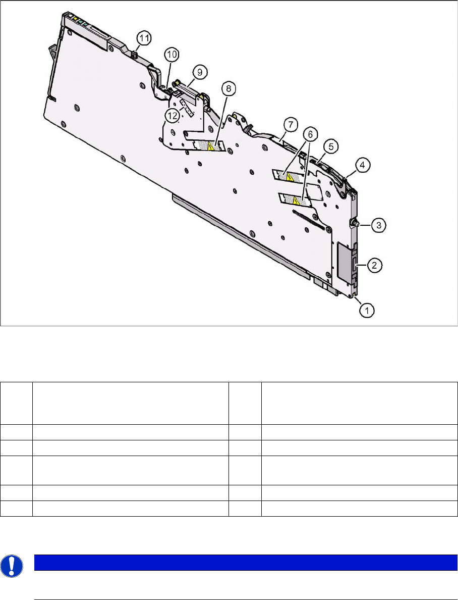
X feeder parts (front view)
Legend
X Splice Sensor Note
10.2.2.1 X Splice Sensor Note
1 Locking roll (the locking hook of the
changeover table locks the feeder and
locking roll in the end position.)
7 Opening of the tape channel
2 Power- and Data interface 8 Drive motor for the cover foil unit
3 Centering pin "front" 9 Cover foil rocker
4 Lever to lift the Pickup window to insert and
remove the tape
10 Foil removal unit
5 Pick up window 11 Centering pin "back"
6 Drive motors for tape transport 12 Adjustment of the cover foil tension
NOTICE
X splice sensors are mounted as an option, directly behind the pickup position of the X feeder
and communicate via the feeder CAN Bus --> machine CAN Bus with the station software.
Component Handling
X Feeder X Feeder Parts (Back View)
357 Student Guide SIPLACE X-Serie and X4I SW70x (AL2)
X Feeder Parts (Back Vi ew)
10.2.3 X Feeder Parts (Back View)
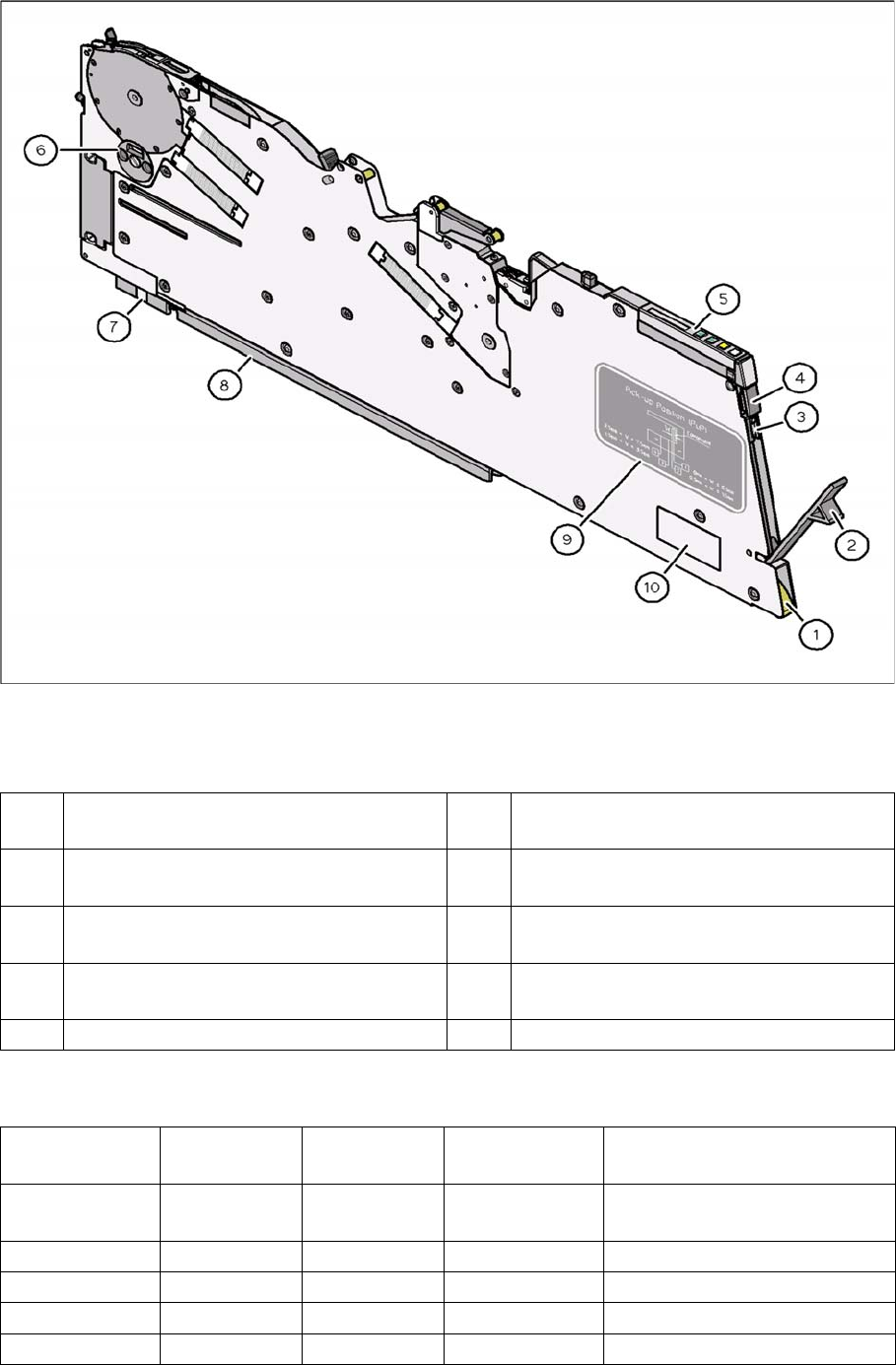
X feeder parts
Legend
Overview Feeder Types
10.2.4 Overview Feeder Types
1 Entry aperture to the tape feed channel
with tape spring
6 Shutter for component removal
2 Cover for the foil container 7 Guidance feeder at the changeover table
(front)
3 Foil container with cutter, to cut the foil 8 Guidance feeder at the changeover table
(back)
4 Button, to remove the feeder 9 Label which described the different pick up
positions depend on the component size
5 Operator panel 10 Data plate
Tape feeder
module
Item number Feeder width Number of tracks
occupied
Maximum tape material height
(overall)
8 mm X 00141270 10.8 mm 1 1.6 mm paper
3.5 mm blister
12 mm X 00141271 22.4 mm 2 6.5 mm blister
16 mm X 00141272 34.4 mm 3 25 mm blister
24 mm X 00141273 34.4 mm 3 25 mm blister
32 mm X 00141274 45.8 mm 4 25 mm blister