00194614-08 Trainingsdoku. SG X-Serie_X4i SW70x (AL2)_EN.pdf - 第277页
Collect, Pick and Place Head (CPP) Overview Overview of Parts 277 Student Guide SIPLACE X-Serie and X4I SW70x (AL2) Energy Trans mission Energy Transmission ▪ Two transmission leads are needed to transmit the energy supp…
Collect, Pick and Place Head (CPP)
Overview of Parts Overview
Student Guide SIPLACE X-Serie and X4I SW70x (AL2) 276
Holding Circuit Valve Functions
Holding Circuit Valve Functions
E/D Transformer (for CPP Heads < Version 05)
8.2.7.11 E/D Transformer (for CPP Heads < Version 05)
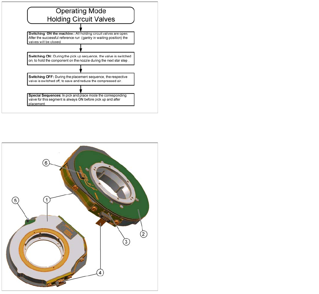
▪ The energy and data transformer consists of a stationary and a rotating part.
▪ The three sliding contacts transmit the direct current voltage (24V/4A).
▪ Communication (the transmission of CAN Bus signals) is contactless. The transmitter is located on
the rear cover of the CPP head and the receiver module on the valve terminal.
▪ The connector (4) supplies power from the intermediate distributor.
▪ The centering pin fixes the stationary part in place via the rear cover of the CPP head.
▪ The rotating part is fixed with five screws to the valve terminal.
▪ The valve terminal consists of 12 holding circuit
valves, which can be switched independently at any
time and in any star position.
▪ Switching on the valves means “throughput”:
Compressed air is present at the venturi nozzles
(voltage = 0V). If a valve should fail or if it is without a
voltage supply, vacuum is always present at the
holding circuit.
▪ Switching off the valves means “valve closed”: There
is no compressed air present at the venturi nozzle
(24 V voltage is present). This saves compressed air!
Legend
1. Stationary part
2. Rotating part
3. Sliding contacts (3x)
4. Connector for power supply
5. Centering pin
6. Interface to valve terminal
Collect, Pick and Place Head (CPP)
Overview Overview of Parts
277 Student Guide SIPLACE X-Serie and X4I SW70x (AL2)
Energy Transmission
Energy Transmission
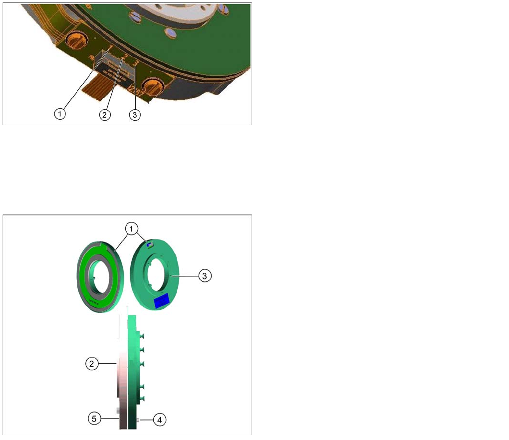
▪ Two transmission leads are needed to transmit the energy supply: P24V (1) and GND (2).
▪ Another lead (3) (sliding contact) forms the connection between the rotating part and the housing
ground (ESD protection).
Contactless Energy Transformer (for CPP Heads from Version 05)
8.2.7.12 Contactless Energy Transformer (for CPP Heads from Version 05)
▪ The contactless energy transformer consists of two parts, a stator (1) and a rotor (2).
▪ Activating is done via an additional board that is located on the intermediate distributor 2 as a
piggyback board.
▪ The stator is fixed at the rear cover of the placement head, the rotating part, rotor, (2) is fixed to the
star frame via the terminal board.
▪ In the middle of the contactless energy transformer the transformer for contactless data transmission
is located.
Legend
1. P24V
2. GND
3. ESD protection
Legend
1. Stationary part (stator)
2. Rotating part (rotor)
3. Fastening screw at the rear cover (5x)
4. Power supply from the intermediate distributor to the
stator
5. Centering pin
6. Connector to SCS
Collect, Pick and Place Head (CPP)
Overview of Parts Overview
Student Guide SIPLACE X-Serie and X4I SW70x (AL2) 278
Energy Transmission
Energy Transmission
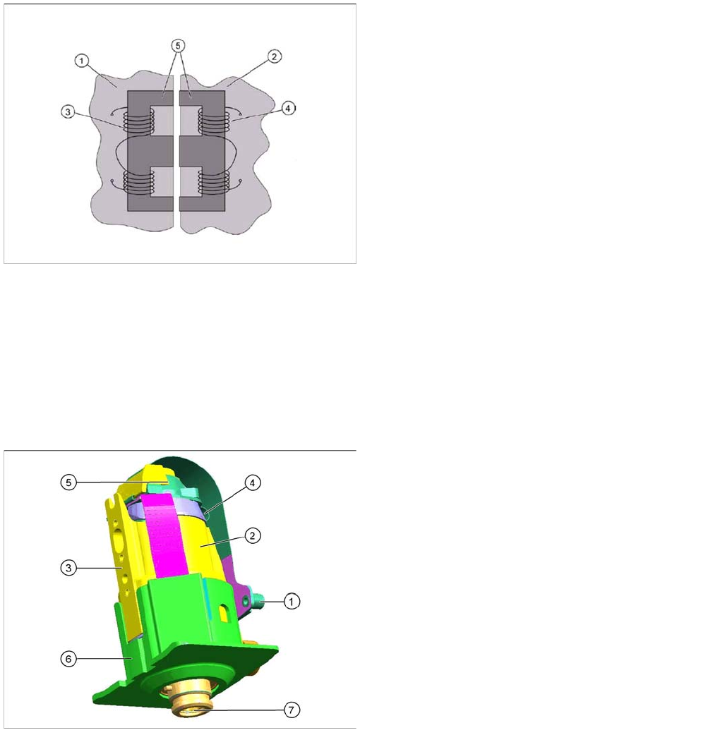
▪ The energy transmission is done with the help of a split transformer. One part is located on the rear
cover of the CPP head (stator) and the other part (rotor) is fitted to the valve terminal.
▪ Both transformer sections have coils. A.C. voltage from the stator side induces a magnetic field in
the transformer core, which then generates a.c. voltage on the rotor side. This power is used to
supply the SCS and to control the DP drives.
▪ A voltage of 24V is transmitted.
DP drive
8.2.7.13 DP drive
▪ The DP drive is responsible for turning the nozzles into the correct pickup position and the
component into the correct placement position.
▪ Vacuum and air blast to the nozzle are provided via the motor shaft of the DP axis.
▪ The complete DP drive and the linear guidance can be replaced during service work.
Legend
1. Rotor
2. Stator
3. Coil (secondary side)
4. Coil (primary side)
5. Split transformer ferrite core
Legend
1. The connector is fitted and screwed to the SCS
control unit.
2. Motor
3. Fixture surface for screwing the linear guidance into
place
4. Vacuum connection
5. Measuring system
Resolution: 278 digits per degree or
100.000 digits per revolution
6. Camera background (black) for DP drive
7. Nozzle interface