00194614-08 Trainingsdoku. SG X-Serie_X4i SW70x (AL2)_EN.pdf - 第344页
TwinHead Manual Lowering of Z Axis Settings Student Guide SIPLACE X-Serie and X4I SW70x (AL2) 344 Manual Lo wering of Z Axis 9.4.3 Manual Lowering of Z Axis The TwinHead is designed for a placement force of 0.5 to 15 N (…
TwinHead
Settings Parameter and Calibrations
343 Student Guide SIPLACE X-Serie and X4I SW70x (AL2)
Calibration Step 2
Calibration Step 2
Calibration Step 3
Calibration Step 3
Calibration Step 4
Calibration Step 4
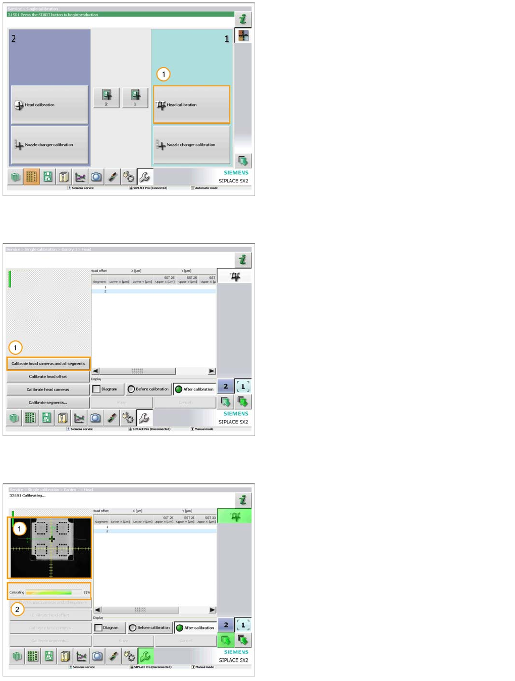
1. Select ‘Head calibration’ for the gantry fitted with the
TwinHead.
A 518 nozzle should now be fitted to both segments on
the head and the calibration tool should be placed in the
pocket on the conveyor rail.
1. When you are ready select ‘Calibrate head cameras
and all segments’.
The calibration will now be automatically performed. It will
take approx. 5 minutes.
1. The image from the vision system is displayed as the
calibration takes place.
2. The progress of the calibration is also displayed.
TwinHead
Manual Lowering of Z Axis Settings
Student Guide SIPLACE X-Serie and X4I SW70x (AL2) 344
Manual Lo wering of Z Axis
9.4.3 Manual Lowering of Z Axis
The TwinHead is designed for a placement force of 0.5 to 15 N (to 30 N for high-force TwinHead)
The rotary axis needs to be very smooth-running, especially for low placement forces. Therefore, the
rotary axis is not constructed for traction forces.
Since both segments of the TwinHead are fitted at an angle of 180°, there are two different methods for
moving the Z axis downwards.
CAUTION
When manually lowering the Z axis, the TwinHead module can be easily damaged!
► Manual lowering may only be performed by trained personnel!
CAUTION
Before performing manual lowering of the Z axis, make sure the Z axis has been released at
the relevant axis controller board.
► When releasing the Z axis, the Z axis return cylinder moves upwards.
► If the axis is not released, the return cylinder will automatically move upwards when the Z
axis is manually lowered, which could cause injuries and damage to the placement head.
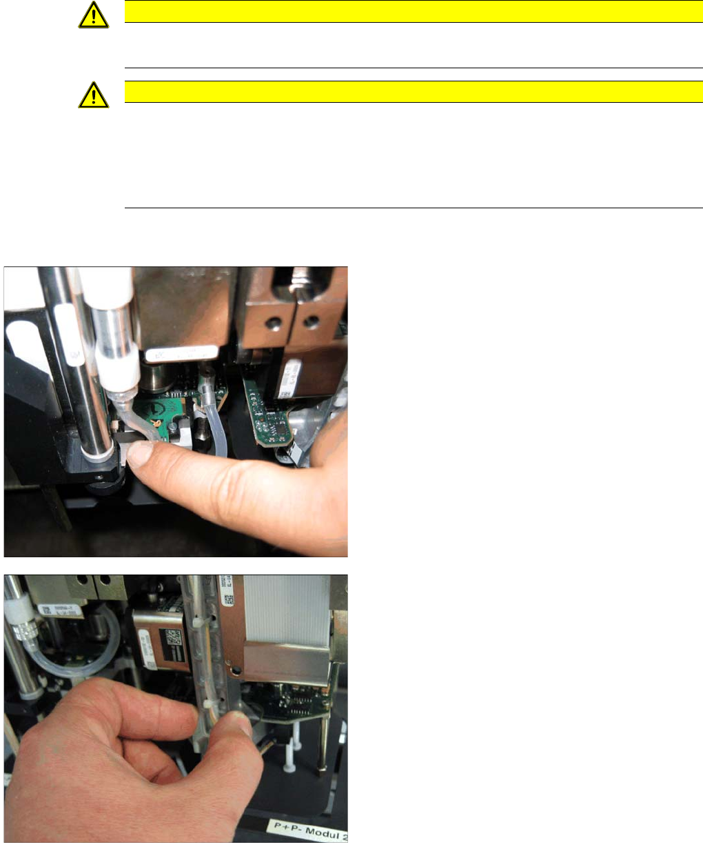
Lowering the Z Axis at P&P Module 1
To safely press the Z axis downwards, apply manual
pressure to the marked part of the retract unit driver.
Lowering the Z Axis at P&P Module 2
The Z axis can be moved downwards at segment 2 by
taking hold of the carrier arm from both sides and then
pushing this down.
TwinHead
Nozzle changer Fitting the Nozzle Changer Magazine
345 Student Guide SIPLACE X-Serie and X4I SW70x (AL2)
Nozzle changer
9.5 Nozzle changer
Fitting the Nozzle Changer Magazine
9.5.1 Fitting the Nozzle Changer Magazine
Function Description
9.5.2 Function Description
The magazine for standard nozzles has 1 positioning fiducial for position detection, while the magazine
for special nozzles/grippers has two positioning fiducials. The nozzles are fixed by balls in the holder.
They are then either locked for return or released for pickup, depending on the direction of rotation of the
D axis.
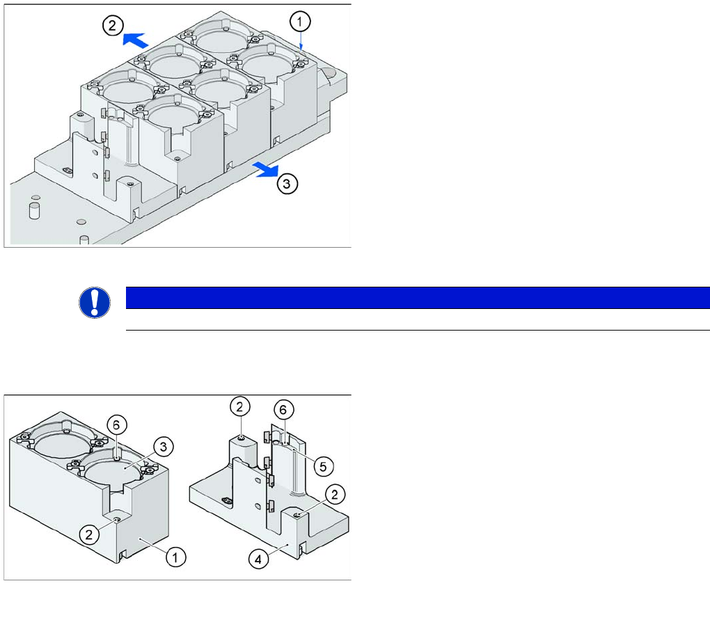
Fitting the magazine (X/D3 machine)
The nozzle changer together with the empty tape duct is
fixed on the component docking unit. The magazines are
seated on a common support. They are centered with two
parallel pins and fixed in place with two countersunk
screws.
Legend
1. Nozzle changer marking hole
2. Operator side (changeover table side)
3. Arrow pointing toward the PCB conveyor
Align the nozzle changer so that the marking hole (item
1) is on the left, as viewed by the operator (at the
changeover table side).
NOTICE
On X machines with MTC a special adapter for the TwinHead nozzle changer is required.
Magazine for standard and special nozzles (HF/X/D3
machine shown here as example)
Legend
1. Standard magazine
2. Positioning fiducial
3. Nozzle garage
4. Magazine for special nozzles
5. Nozzle garage
6. Balls for lifting the nozzles