00194614-08 Trainingsdoku. SG X-Serie_X4i SW70x (AL2)_EN.pdf - 第244页
C&P20A Placing Component 20 Pickup and Placement Cycle for C&P20A Student Guide SIPLACE X-Serie and X4I SW70x (AL2) 244 Placing Co mponent 20 7.4.18 Placing Component 20 Pickup and P lacement Cycle For the N ext …
C&P20A
Pickup and Placement Cycle for C&P20A Placing Component 10
243 Student Guide SIPLACE X-Serie and X4I SW70x (AL2)
Placing Component 10
7.4.16 Placing Component 10
Placing Component 11
7.4.17 Placing Component 11
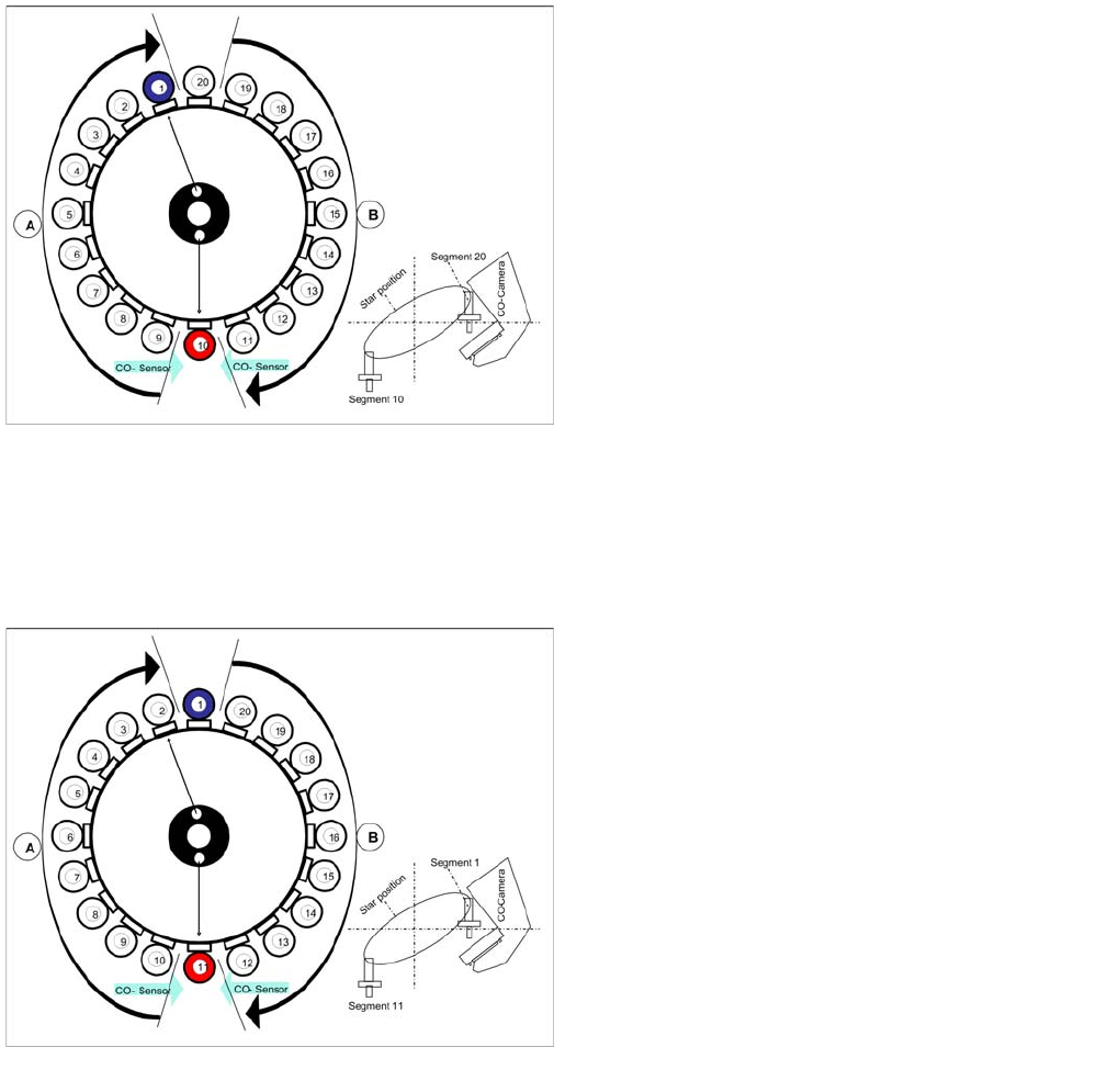
Placing Component 10
Star position 162°
▪ Vision system: Optical centering of component 20
▪ Pickup/placement station: Place component 10
(here: red)
▪ At the next step Vision system have to center
optically the component at segment 1 on the other
gantry. blue).
▪ Component sensor: Checks before placement; if
component is present on nozzle / after placement; if
the component has been placed. (see "7.4.13
Checking the Component Sensor of the Component
at Segment 1" [ ➙ 241] "7.4.15 Component Sensor
Checks Segment 1" [ ➙ 242])
▪ A : The components previously picked up are rotated
to the placement angle.
▪ B : The components are adjusted to their placement
angles.
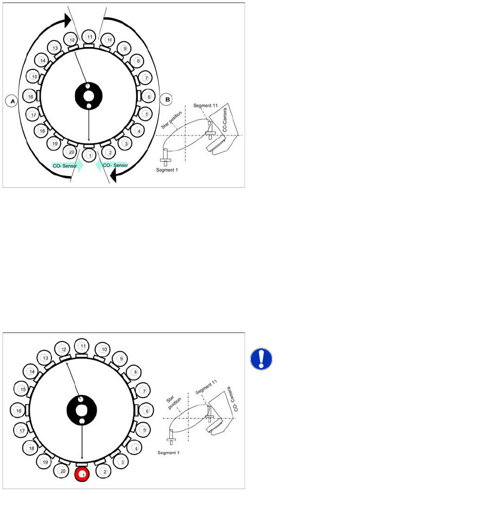
Placing component 11
Star position 180°
▪ Vision system: Optical centering of component 1 on
other gantry (here: blue)
▪ Pickup/placement station: Place component 11
(here: red)
▪ Component sensor: Checks before placement; if
component is present on nozzle / after placement; if
the component has been placed. (see "7.4.13
Checking the Component Sensor of the Component
at Segment 1" [ ➙ 241] "7.4.15 Component Sensor
Checks Segment 1" [ ➙ 242])
▪ A : The components previously picked up are rotated
to the placement angle.
▪ B : The components are adjusted to their placement
angles.
C&P20A
Placing Component 20 Pickup and Placement Cycle for C&P20A
Student Guide SIPLACE X-Serie and X4I SW70x (AL2) 244
Placing Component 20
7.4.18 Placing Component 20
Pickup and P lacement Cycle For the N ext Components
7.4.19 Pickup and Placement Cycle For the Next Components
▪ After all the components of the first head cycle have been placed on the board, the gantry axes move
the placement head to the pickup position of the next pickup cycle.
▪ The next pickup cycle is performed for components 21 - 40.
▪ The subsequent pickup cycles follow the same procedure. If necessary the machine performs repair
cycles.
Segment with a "Defective Component“
7.4.20 Segment with a "Defective Component“
If the optical centering of a component fails (ident. error) or component recognition before placement
fails, the component will not be placed and will remain on the nozzle.
▪ The turning station will still turn this nozzle to the pickup angle of the new component if this segment
is in area A.
If this segment is in pickup position:
▪ The reject procedure will be activated and
▪ the X/Y axes will move to the reject position for this gantry,
▪ The component will be rejected to the reject box below, via air blast
▪ The new component is picked up.
The rejected component will then be placed in a repair run after all the other placement cycles for this
placement head have been performed.
Finishing Board Placement
7.4.21 Finishing Board Placement
▪ After placing the last component, the gantry axes move the placement heads to the waiting position.
▪ An optical nozzle scan is performed after the first board or after the relevant board (depending on
the scan parameters).
▪ The SIPLACE placement station activates the conveyor system and moves the board to the
intermediate/output conveyor.
▪ Finally, the SIPLACE placement station sends the number of consumed components (placed and
rejected ones) to the computer with the OIS (Operator Information System).
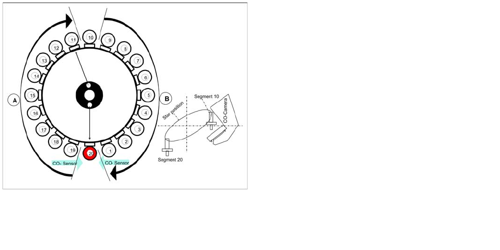
Placing component 20
Star position 342°
▪ Vision system: Optical centering of component 10 on
other gantry (here: blue).
▪ Pickup/placement station: Placing component 20
(here: red)
▪ Component sensor: Checks before placement; if
component is present on nozzle / after placement; if
the component has been placed. (see "7.4.13
Checking the Component Sensor of the Component
at Segment 1" [ ➙ 241] "7.4.15 Component Sensor
Checks Segment 1" [ ➙ 242])
▪ A : The components previously picked up are rotated
to the placement angle.
▪ B : The components are adjusted to their placement
angles.
▪ Synchronization: After the 20th component this
gantry Y axis controller will enable the other gantry Y
axis to move to 1st placement position.
C&P20A
Pickup and Placement Cycle for C&P20A Positioning to Pickup/Placement Angle
245 Student Guide SIPLACE X-Serie and X4I SW70x (AL2)
▪ The OIS (Operator Information System) calculates the placement statistics referring to the
programmed station setup, the programmed panel or the last reset time. This detailed data is used
to optimize the process.
▪ The machine is now ready for the next board.
Position ing to Pic kup/Placement Ang le
7.4.22 Positioning to Pickup/Placement Angle
Positioning to the pickup/placement angle is performed individually by the DP master for each segment
of the C&P20A head, since each segment is equipped with its own DP station.
Each DP drive has its own measurement system for positioning the pickup/place angle.
Once the DP stations have found their 0° position during the reference run, the pickup/placement cycle
control turns the segments in area A into their pickup or centering angle (90° step) and corrects the
placement angle in area B.
Detailed Standard Pickup Procedure: Z Axis Down
7.4.23 Detailed Standard Pickup Procedure: Z Axis Down
▪ Enables vacuum query: segment open threshold ? Yes
Component sensor switches due to Z axis movement:
▪ Measurement value for nozzle length "empty"
Axis controller:
▪ Enable "light barrier down" signal.
LB down switches:
▪ End signal Z axis positioning down
Positioning to pickup/placement angle
The 20 DP stations are controlled via the DP master. The
machine control system can therefore effectively perform
4 actions simultaneously:
► Starting a certain rotary axis after pickup/placement.
► Starting a certain rotary axis after Vision.
► Waiting for a certain rotary axis before Vision.
► Waiting for a certain rotary axis before pickup/
placement.
Star position 0°: detailed pickup sequence - Z axis down
Start gantry axes to the pick up position of next feeder.
NOTICE! The Vacuum is by default always on.
▪ Start signal for X and Y axes to move to next feeder.
End signal X, Y axes:
▪ X/Y end position signals available.
Z axis starts:
▪ Z axis starts positioning downwards
End position signal for star axis