00194614-08 Trainingsdoku. SG X-Serie_X4i SW70x (AL2)_EN.pdf - 第241页
C&P20A Pickup and Placement Cycle for C&P20A Picking Up Component 20 241 Student Guide SIPLACE X-Serie and X4I SW70x (AL2) Picking Up Component 20 7.4.12 Picking Up Component 20 Checking th e Compone nt Sensor of…
C&P20A
Picking Up Component 12 Pickup and Placement Cycle for C&P20A
Student Guide SIPLACE X-Serie and X4I SW70x (AL2) 240
Picking Up Component 12
7.4.10 Picking Up Component 12
Picking Up Component 13
7.4.11 Picking Up Component 13
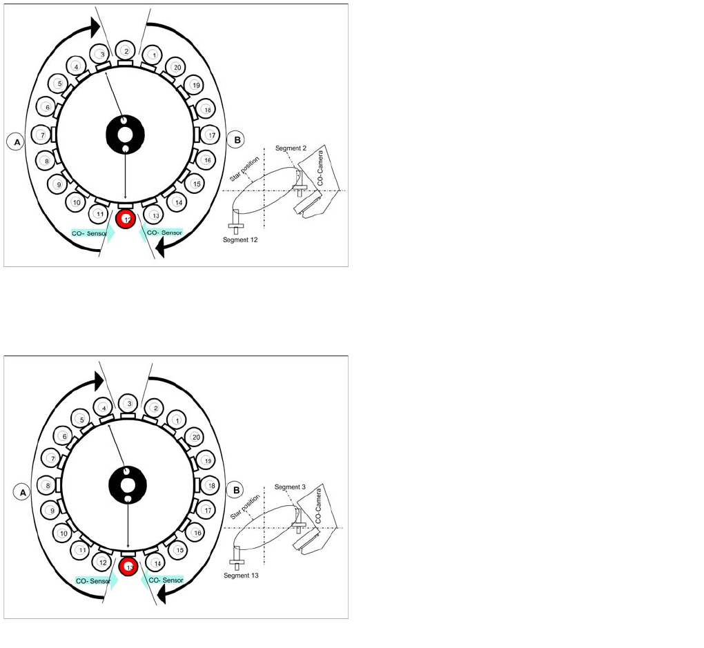
Picking up component 12
Star position 198°
▪ Vision system: Component at segment 2 of this
gantry is centered
▪ Pickup/placement station: Picking Up Component 12
▪ A : The components previously picked up are rotated
to the placement angle.
▪ B : The components are adjusted to their placement
angles.
Picking up component 13
Star position 216°
▪ Vision system: Optical centering of component 3
▪ Pickup/placement station: Picking Up Component 13
▪ A : The components previously picked up are rotated
to the placement angle.
▪ B : The components are adjusted to their placement
angles.
▪ Measurement of holding circuit for segment 4
The process continues with the remaining components:
picked up, centered and turned to the correct or corrected
placement angle.
C&P20A
Pickup and Placement Cycle for C&P20A Picking Up Component 20
241 Student Guide SIPLACE X-Serie and X4I SW70x (AL2)
Picking Up Component 20
7.4.12 Picking Up Component 20
Checking the Component Sensor of the Component at Segment 1
7.4.13 Checking the Component Sensor of the Component at Segment 1
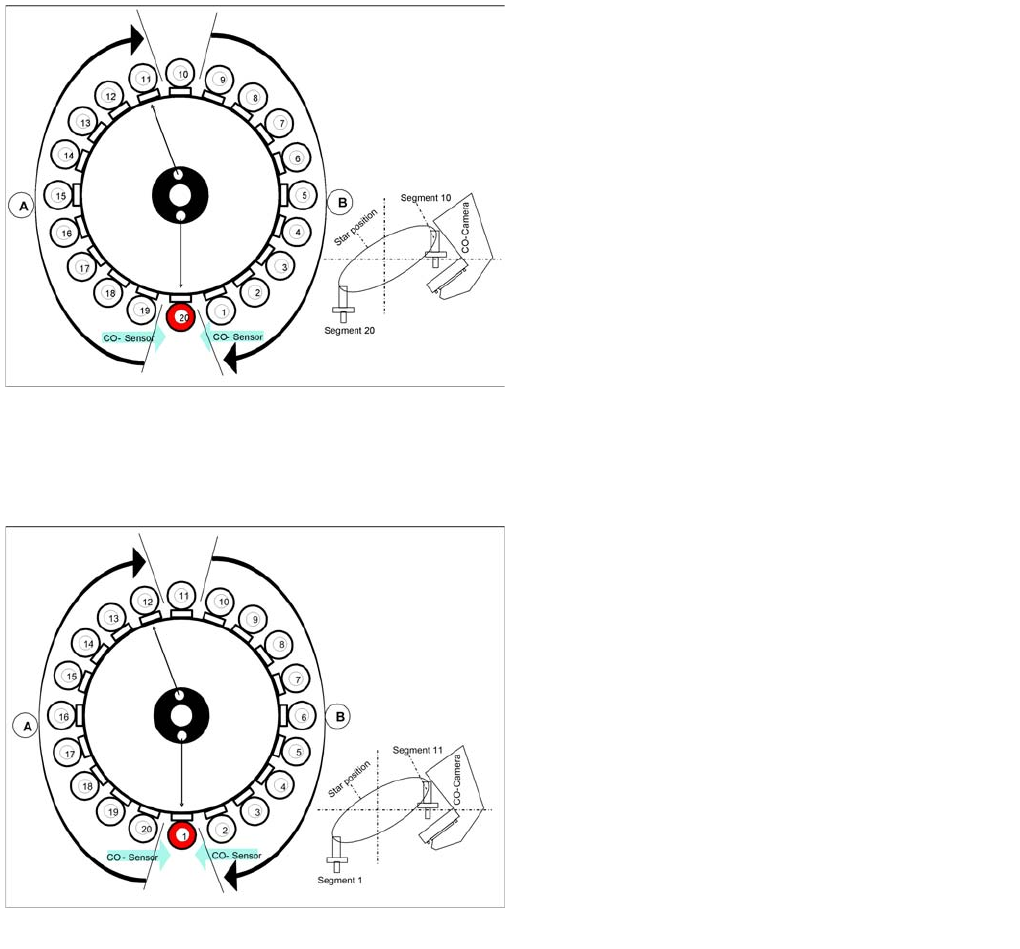
Picking up component 20
Star position 342°
▪ Vision system: Optical centering of component 10
▪ Pickup/placement station: Picking Up Component 20
▪ Communication with the changeover table: cutter
enabled
▪ Synchronization: After picking up component 20, this
gantry waits for permission to position from the Y axis
controller of the other gantry.
▪ Component sensor: during the next star step,
component presence/ height check is performed for
segment 1.
▪ A : The components previously picked up are rotated
to the placement angle.
▪ B : The components are adjusted to their placement
angles.
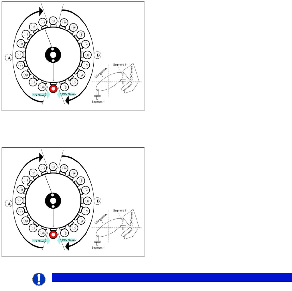
Checking the component before placement
Star turns to -> 360° (identical with 0° position)
Measurement with component sensor: When the star
axis has turned to 360.000 digits, component 1 is again
in placement position.
▪ Vacuum check: Holding force for component
present?
▪ Z axis starts to move downwards and then
▪ The component sensor checks the presence or the
component height at segment 1.
▪ The length measured before placement must exceed
nozzle length + component height - component
height tolerance.
▪ If errors occur, the Z axis will be stopped and moved
back.
C&P20A
Placing Component 1 Pickup and Placement Cycle for C&P20A
Student Guide SIPLACE X-Serie and X4I SW70x (AL2) 242
Placing Component 1
7.4.14 Placing Component 1
Compone nt Sensor Checks Segment 1
7.4.15 Component Sensor Checks Segment 1
See also
7.4.13 Checking the Component Sensor of the Component at Segment 1 [ ➙ 241]
Placing component 1
Star position 0°
▪ Vision system: Optical centering of component 11
▪ Pickup/placement station: Z axis moves downwards
to place component 1.
▪ A : The components previously picked up are rotated
to the placement angle.
▪ B : The components are adjusted to their placement
angles.
Component sensor checks after placement
Star position 0°
▪ Vision system: Optical centering of component 11
▪ Pickup/placement station: Z axis moves upwards and
sensor checks whether component has been placed
at segment 1.
▪ A : The components previously picked up are rotated
to the placement angle.
▪ B : The components are adjusted to their placement
angles.
▪ Vacuum check: whether vacuum has been switched
back on.
NOTICE
The component check by the component sensor is also performed for all other nozzles.