00194614-08 Trainingsdoku. SG X-Serie_X4i SW70x (AL2)_EN.pdf - 第249页
C&P20A Settings Boar d Descriptions for C&P20A 249 Student Guide SIPLACE X-Serie and X4I SW70x (AL2) Base Ada pter for CPx on SX 4 Machines with HCU 7.5.1.2 Base Adapter for CPx on SX4 Machines with HCU Base adap…
C&P20A
Board Descriptions for C&P20A Settings
Student Guide SIPLACE X-Serie and X4I SW70x (AL2) 248
Settings
7.5 Settings
Board D escriptio ns for C&P 20A
7.5.1 Board Descriptions for C&P20A
Head Adapter for C&P20A on X Machines wit h A364
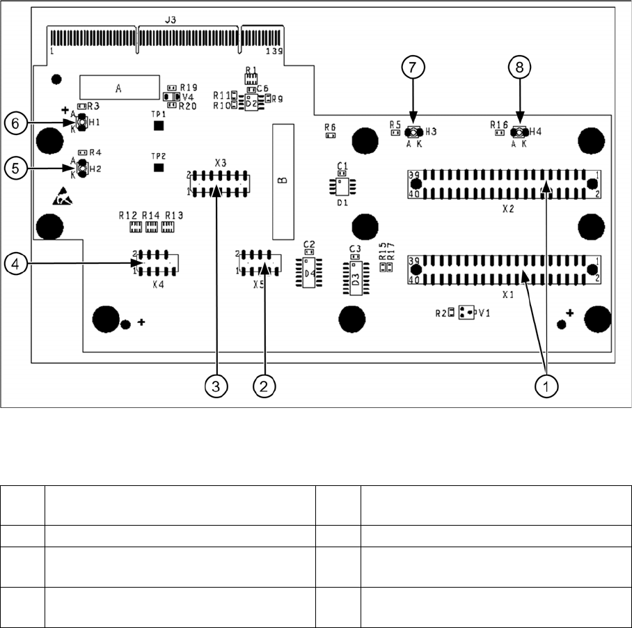
7.5.1.1 Head Adapter for C&P20A on X Machines with A364
Head adapter for C&P20A
Legend
1 X1, X2 connection to intermediate
distributor
5 H2 LED (green) for DP motor 24 V display
2 X5 Z axis track signals 6 H1 LED (red) for 24 V display at C&P20
3 X3 test connector: serial parallel interface
(SPI) bus
7 H3 LED (green) for component sensor
display
4 X4 star track signals 8 H4 LED (red) for hardware error display at
C&P20A
C&P20A
Settings Board Descriptions for C&P20A
249 Student Guide SIPLACE X-Serie and X4I SW70x (AL2)
Base Ada pter for CPx on SX 4 Machines with HCU
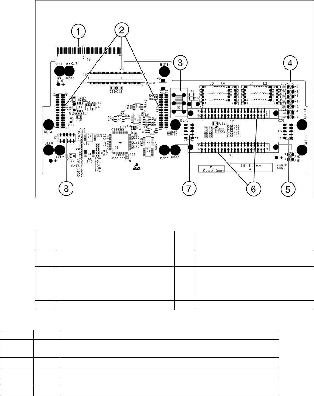
7.5.1.2 Base Adapter for CPx on SX4 Machines with HCU
Base adapter for CPx [03045647-xx] on SX4 machines with HCU
Legend
Meaning of LEDs H1 - H9
1 X3 Connection to the head interface board
C700
5 Test connector for FPGA
2 X4, X14, X15 – connector for HCU 6 X1-X2 flat ribbon connection for CPP or
C&P20
3 Switch S1 intermediate circuit voltage
Z axis
40V C&P20 (switch top)
150V CPP(switch bottom)
7 X6 Programming connector for FPGA
4 LED H3- H9 8 X7 Test connector HCU
H1 OK Status display for the component sensor
H2 RS232 Shines when the programming connector for the HCU1 is connected (not
designed for Service)
H3 1V5 Voltage monitor 1.5 V, shines red in event of errors
H4 3V3 Voltage monitor 3.3 V, shines red in event of errors
H5 5V Voltage monitor 5 V, shines red in event of errors
H6 15V Voltage monitor 15 V, shines red in event of errors
C&P20A
Board Descriptions for C&P20A Settings
Student Guide SIPLACE X-Serie and X4I SW70x (AL2) 250
The voltage monitors trigger as soon as the target voltage is exceeded or undershot by 5%.
Head Int erface o n SX4 Machines with HCU
7.5.1.3 Head Interface on SX4 Machines with HCU
The head interface on the SIPLACE SX4 is available in two versions due to the mirrored gantries.
▪ Head interface C700X-L [03055067-xx) for gantry 1 and 3
▪ Head interface C700X-R [03055069-xx] for gantry 2 and 4
Both versions have the same functions, connectors and switches.
The head interface is supplied with a voltage of 40 V via the trailing cable. Further voltages for the
electronics and other subsystems are supplied via a DC/CD converter.
Further voltages and signals are:
▪ Track signals X axis
▪ Temperature sensor
▪ FDB bus / CAN bus
▪ Voltages for the star axis, Z axis and X axis are provided by the power supply and distributed to the
head interface.
H7 DP Voltage monitor DP (currently without function)
H8 24V Voltage monitor 24 V, shines red in event of errors
H9 LOC Voltage monitor local - shines red as soon as one of the voltage monitors
triggers (not for 24 V)