00194614-08 Trainingsdoku. SG X-Serie_X4i SW70x (AL2)_EN.pdf - 第268页
Collect, Pick and Place Head (CPP) Overview of Parts Overview Student Guide SIPLACE X-Serie and X4I SW70x (AL2) 268 Overview of Parts 8.2.7 Overview of Parts Front plate 8.2.7.1 Front plate See also 8.2.7.2 Pre ssure c…
Collect, Pick and Place Head (CPP)
Overview Principle of CPP Head
267 Student Guide SIPLACE X-Serie and X4I SW70x (AL2)
▪ Component spectrum for component 01005 – 50x40 mm
Component height max. 11.5 mm
▪ The holding circuit has one venturi nozzle for each segment.
→ No more interference between the segments.
▪ Each segment has its own valve. Each segment can therefore be switched off separately.
This reduces the air consumption.
▪ Each segment has its own motor with incremental measuring system.
The segments can be rotated independently of one another.
▪ The light barrier down is integrated into each segment.
This leads to a higher placement reliability. There is no need to adjust the light barrier down. This
design is more robust, since a movable cable is not required.
▪ A digital pressure control valve enables faster switching times between vacuum and air blast.
▪ The component sensors in the pickup&place position are more robust. The prisms have mechanical
protection.
This leads to a higher placement reliability.
▪ Robust nozzle interface and nozzle magazine
▪ Nozzle types 20xx and 28xx with corresponding magazines
Principle o f CPP Head
8.2.6 Principle of CPP Head
▪ The CPP head functions according to the Collect&Place principle, like the C&P12 head, whereby the
additional operating modes Pick&Place and mixed mode help to extend the component spectrum.
▪ Each segment is equipped with its own DP drive and an incremental measuring system, to allow
angle adjustment while the star is revolving.
▪ Energy and data from the stationary part of the head are transferred via a contactless energy
transformer and a contactless data transformer to the control board (Single Core Solution) and the
DP drives.
▪ In addition, each DP drive has a light barrier Z down. Together with the secondary part of the linear
motor (Z axis), there is no cable which is moved with the Z movement.
▪ The so/called valve terminal is used to switch the supply pressure on and off for each segment.
▪ In the pickup and placement position, the Z axis moves with the complete DP drive unit upwards or
downwards.
▪ In the pickup cycle, the vacuum is increased by the holding circuit, using a pressure control valve.
During placement, the vacuum is eliminated by the holding circuit, with an air blast, and the
components are blown off.
▪ In the pickup/placement position, the standard component sensor is used to check the presence and/
or height of the components on the nozzle, both before and after pickup/placement.
Collect, Pick and Place Head (CPP)
Overview of Parts Overview
Student Guide SIPLACE X-Serie and X4I SW70x (AL2) 268
Overview of Parts
8.2.7 Overview of Parts
Front plate
8.2.7.1 Front plate
See also
8.2.7.2 Pressure control valve (digital) [ ➙ 268]
Pressure c ontrol valve (d igital)
8.2.7.2 Pressure control valve (digital)
Legend
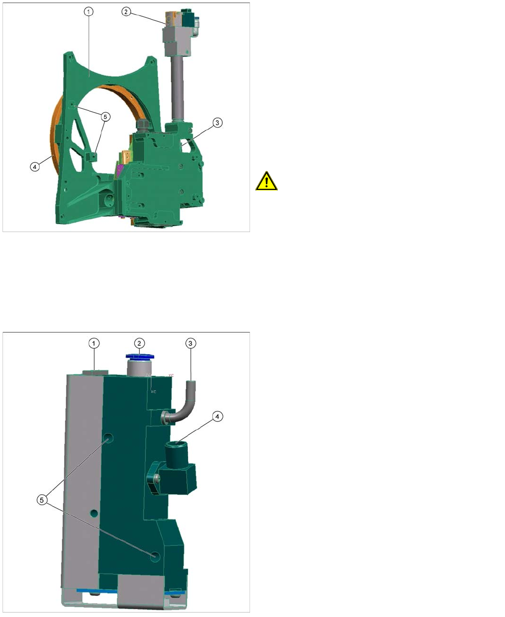
1. Front plate
2. Return cylinder
3. Z axis with jaws and measuring system
4. Raceway
5. Fixture for pressure control valve
Front plate
The front plate of the CPP head is fixed to the head
housing with four screws and needs to be removed as a
whole unit for service purposes.
CAUTION! Do not dismantle any of the
attachments from the front plate, as all attachments are
coordinated with one another and require special settings
(except the pressure control valve, see ).
LINK
Legend
1. Energy and data supply
2. Compressed air connection
3. Vacuum/air blast outlet for pickup/placement circuit
4. Discharged air for cooling the X motor (SX4 and X
series machines only).
5. Fixture for fastening the pressure control valve to the
front plate
▪ The pressure control valve supplies the pickup/
placement circuit with vacuum during the pickup
process and switches over to air blast during
placement.
▪ The digital pressure control valve can be adjusted
infinitely between max. vacuum and max. air blast in
the pickup/place circuit.
▪ The complete press control valve can be replaced
during service work.
Collect, Pick and Place Head (CPP)
Overview Overview of Parts
269 Student Guide SIPLACE X-Serie and X4I SW70x (AL2)
Pressure Control Valve - Function
Pressure Control Valve - Function
Z Axis
8.2.7.3 Z Axis
▪ The secondary part (magnets) of the linear motor is the moveable part on the z-axis. The primary
part is fixed. Benefit: There is no power supply cable of the motor that moves up and down with the
Z axis.
▪ The jaws are installed on the secondary part of the Z motor, for mechanical docking of the DP drives.
▪ The retract unit is integrated in the Z-Axis frame and is responsible for protecting the Z-axis from
damage if there is no power supplied.
Legend
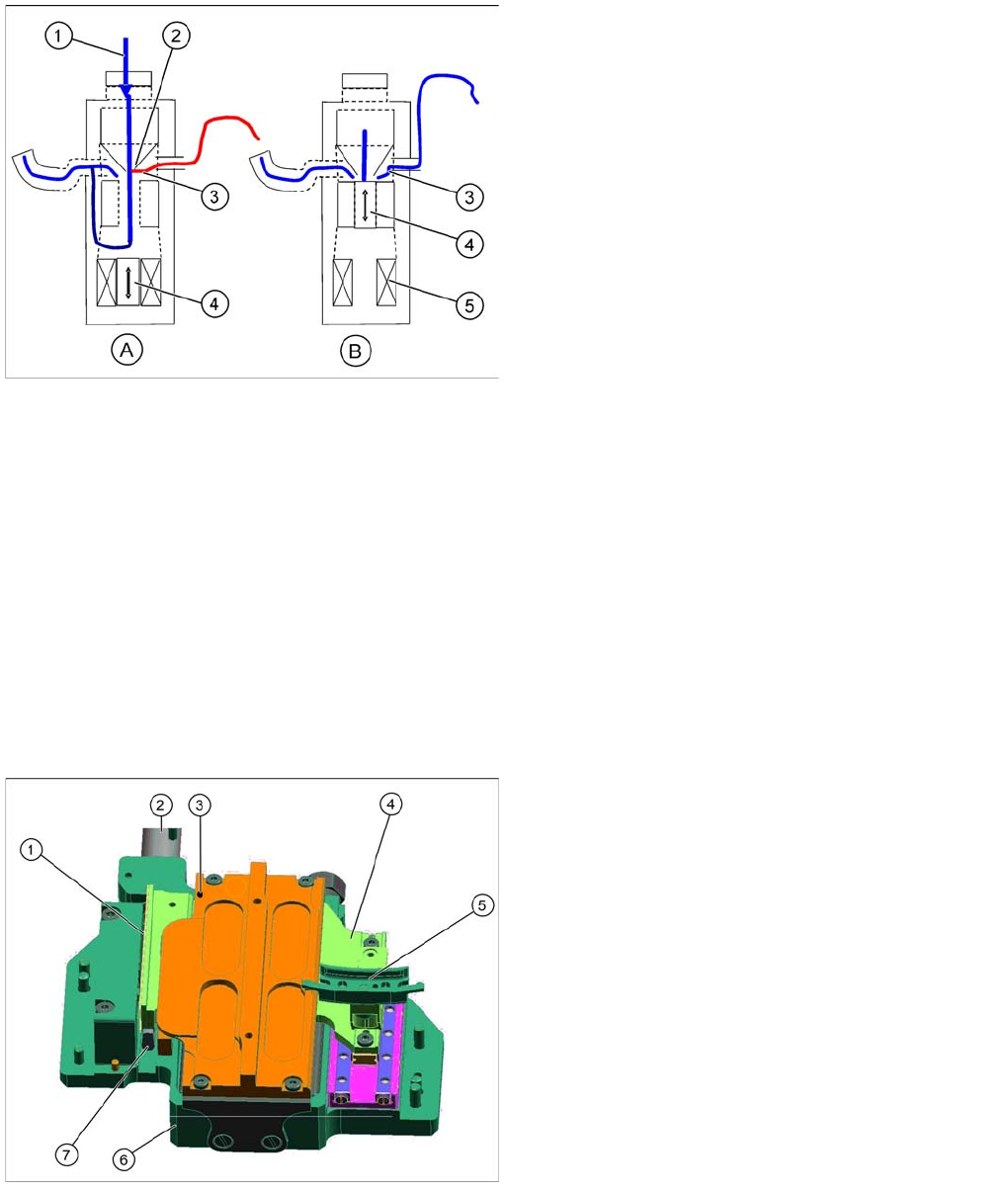
A : Piston setting for max. vacuum during pickup
B : Piston setting for air blast during placement
1. Compressed air inlet
2. Venturi nozzle
3. Vacuum or air blast outlet, depending on piston
setting
4. Pistons
5. Motor
▪ After initialization, the piston is in a central position, in
which neither vacuum nor air blast is applied to the
nozzle.
▪ During pickup, the piston is always in the Open
position, so that maximum vacuum is generated and
is present at the nozzle. The switchover time
(pressure build up time) between max. vacuum of –
850 mbar to max. air blast of +200 mbar ≤ 12 ms.
▪ The function Early vacuum should always be
switched on for the CPx head. However, if this
function is switched off, the piston will be in the "open
position". The vacuum will only be switched on again
after the "light barrier down" signal has been issued .
-> 2 additional switching steps -> time loss.
Legend
1. Incremental measurement system, resolution 0.5 µm
2. Retract unit
3. Lubrication point for Z axis support ball bearing
4. Secondary part with magnets
The secondary part is fitted to the Z axis.
5. Jaws
The jaws are fitted to the linear guidance of the Z axis.
6. Linear motor, primary part
7. Actuator on the retract unit