00194614-08 Trainingsdoku. SG X-Serie_X4i SW70x (AL2)_EN.pdf - 第373页
Component Handling Pneumatic Tape Cutter Structure and Fun ction of the Pneumatic Tape Cutter 373 Student Guide SIPLACE X-Serie and X4I SW70x (AL2) Pneumatic Tape Cutter Legend The tape cutter is activated wh en the gant…
Component Handling
Structure and Function of the Pneumatic Tape Cutter Pneumatic Tape Cutter
Student Guide SIPLACE X-Serie and X4I SW70x (AL2) 372
Complete docking unit
Legend
Structure and Function of the Pneumatic Tape Cutter
10.3.2 Structure and Function of the Pneumatic Tape Cutter
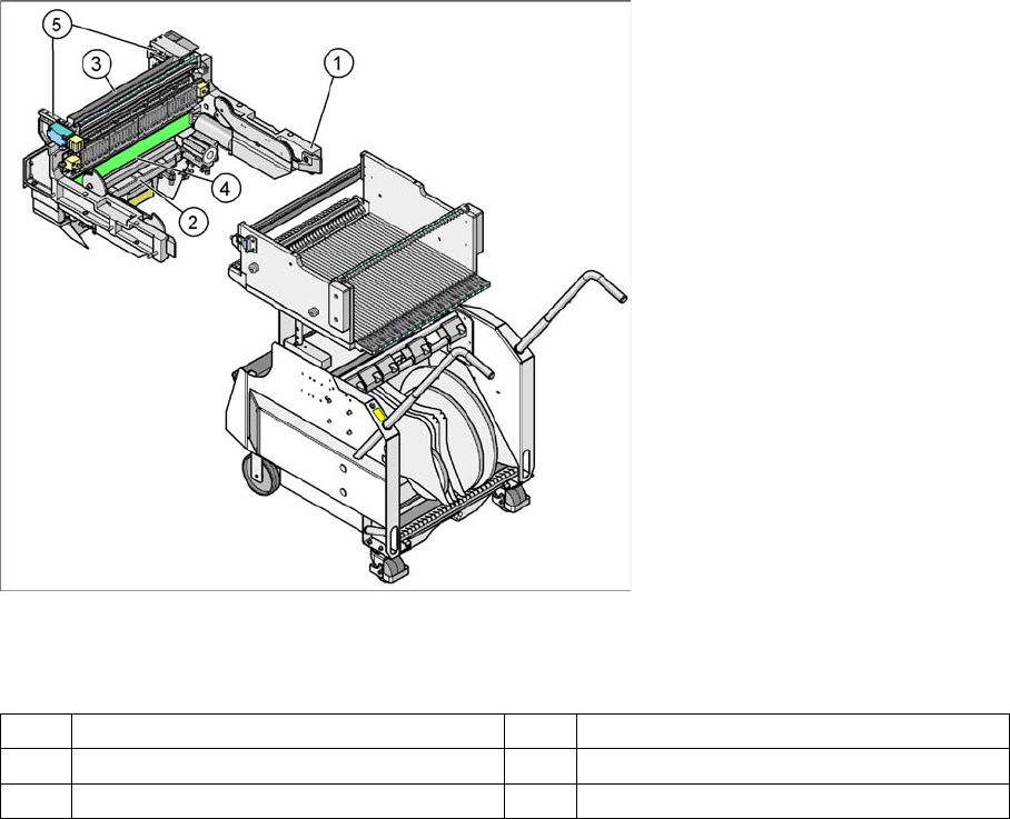
The empty tape duct guides the empty tapes through the opening (3) in the cutter.
The cutter is based on a horizontal frame (1) with a fixed cutting edge and a flexible blade, which is
moved by two short-stroke cylinders (2). At each upwards or downwards movement, the device cuts off
the tape.
The proximity switch (5) signals the position of the short-stroke cylinder piston and therefore the position
of the cutter blade. The proximity switch enables the control electronics (4) to register whether the tape
has been cut. Cutting only takes place during placement. For operational safety reasons, the tape cutter
is integrated into the emergency stop circuit.
The pneumatic tape cutter is fixed on the frame of the docking unit with four screws and this, together
with the empty tape duct is a complete unit.
1 Frame docking unit 2 Pneumatic Tape Cutter
3 Component reject bin 4 Empty tape duct
5 Support for the nozzle changer
Component Handling
Pneumatic Tape Cutter Structure and Function of the Pneumatic Tape Cutter
373 Student Guide SIPLACE X-Serie and X4I SW70x (AL2)
Pneumatic Tape Cutter
Legend
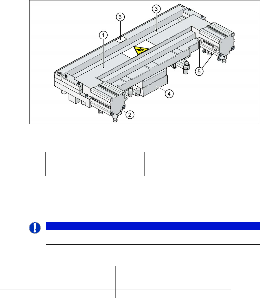
The tape cutter is activated when the gantry moves to the first placement position. Alternating one of the
cylinders start to front position. Once the first cylinder reaches the front position, the second cylinder is
started. Both signals ’blade in front position’ trigger control unit to withdraw both cylinders at the same
time.
The cutter can be removed in about 15 minutes for service purposes. For detailed information about
dismantling, refer to the service manual.
Technical Data
10.3.2.1 Technical Data
1 Horizontal frame 4 Electronic control unit
2 Pneumatic cylinder 5 Proximity switch
3 Slot for empty tape 6
NOTICE
The spare parts numbers for the cutters and the cutter blades are not identical between HF and
X machines.
Compressed air supply 0.5 MPa = 5.0 bar
Compressed air consumption 135 l/min.
Cycle time 1.5 sec per cut
Supply voltages 5 VDC, 24 VDC
Component Handling
Empty Tape Duct Pneumatic Tape Cutter
Student Guide SIPLACE X-Serie and X4I SW70x (AL2) 374
Empty Tape Duct
10.3.3 Empty Tape Duct
The empty tape duct receives empty tapes from the feeders at the inlet gap (1) and guides these from
the outlet gap (2) to the cutting position of the pneumatic cutter. This is where the tape is cut up and falls
down the waste tape chute, into the component trolley waste tape bin. For tapes with tape pockets
deeper than 17mm you have to remove the metal plate in the middle of the empty tape duct. This is fixed
with one screw on the left and one on the right side.
The empty tape duct is fixed to the pneumatic tape cutter with four screws.
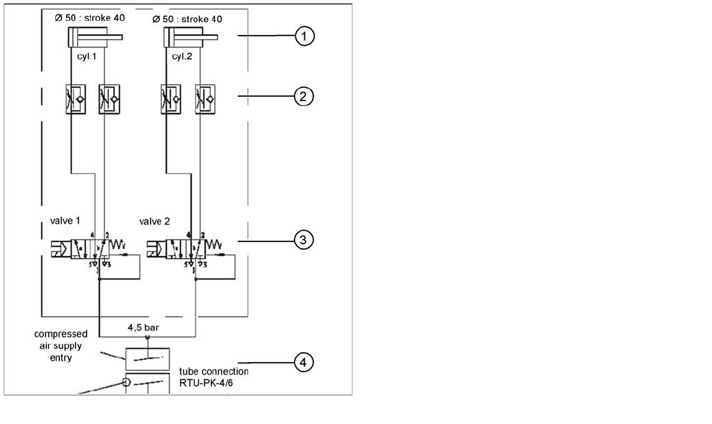
Pneumatic scheme Tape cutter
Legend
1. Drive cylinder for cutter blade movement 40 mm
stroke
2. Adjustable throttle valve on the pneumatic cylinder
3. 5/2 way magnetic valve
4. 4.5 bar compressed air supply via the SSK safety
relay
Cutter only active if protective covers are closed