00194614-08 Trainingsdoku. SG X-Serie_X4i SW70x (AL2)_EN.pdf - 第306页
Collect, Pick and Place Head (CPP) Board Descriptions Settings on the CPP Head Student Guide SIPLACE X-Serie and X4I SW70x (AL2) 306 Meaning of LEDs H1 - H11 The voltage monitors trigger as soon as the target voltage is …
Collect, Pick and Place Head (CPP)
Settings on the CPP Head Board Descriptions
305 Student Guide SIPLACE X-Serie and X4I SW70x (AL2)
Head interface C700X on SX4 machines
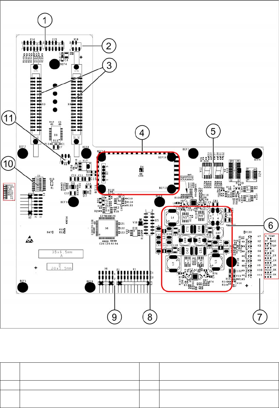
Legend
1 X15 To signal generator
X14 Test connector track signals
7 LEDs H1-H4, H7-H11
2 X16 From temperature sensor X motor 8 X5 From vision board (CAN_H/L)
3 X3-X4 Flat ribbon cables from gantry
interface
9 X1 Test connector, X6 Programming
connector for FPGA
Collect, Pick and Place Head (CPP)
Board Descriptions Settings on the CPP Head
Student Guide SIPLACE X-Serie and X4I SW70x (AL2) 306
Meaning of LEDs H1 - H11
The voltage monitors trigger as soon as the target voltage is exceeded or undershot by 5%.
Head interface DIP switch S1
4 Power cube X7 24V (input 42V) 10 DIP switch block S1
5 7-segment display
HCU 1 (V12) and HCU2 (TWIN Seg.2 – V2)
11 X8 Fan connector (optional)
6 DC/DC converter +15 V, -15 V, +5 V,
+3.3 V, +1.5 V (input 24 V from power
cube)
LED
H7 X_TEMP X motor temperature monitoring, red temp. too high
H2 PF_BASE Power fail from power supply
H3 EM_STOP Emergency stop shines when cover (hood) is open, emergency stop activation
H4 PF_LOC Power fail local, voltage monitoring of the generated voltages from the DC/DC
converter +15V,-15V,+5V,+3.3V,+1.5V
H1 HCU1_ER Status display of eSW application 1
H8 HCU2_ER Status display of eSW application 1
H9 HCU1_OK Status display of eSW application 1
H10 HCU2_OK Status display of eSW application 1
H11 FPGA_OK Field Programmable Gate Array. Monitors the micro controller on the C700X ->
should always be green
S Gantry 1 Gantry 2 Gantry 3 Gantry 4
1 0 1 0 1 Gantry ID
0
2 0 0 1 1 Gantry ID1
3 0 0 0 0 Boot HCU can be set to bootstrap mode; RES1 to
ON; BOOT to ON; RES1 OFF; BIOS
download via external interface possible
4 0 0 0 0 RES1 Reset HCU1
5 0 0 0 0 RES2 Reset HCU2
6 0 0 0 0 FAN Switch for activating or deactivating the fan
(optional) on X
7 0 0 0 0 V-OFF DC/DC converter default "OFF", when
switched to "ON" preventing a run-up of the
voltages after switching on the machine (for
test purposes only)
8 0 0 0 0 HCU Selector switch in bootstrap mode via
external interface "ON" - HCU 2 and "OFF" -
HCU 1
Collect, Pick and Place Head (CPP)
Settings on the CPP Head Board Descriptions
307 Student Guide SIPLACE X-Serie and X4I SW70x (AL2)
Base Ada pter for CPx head s (for SX 1/2)
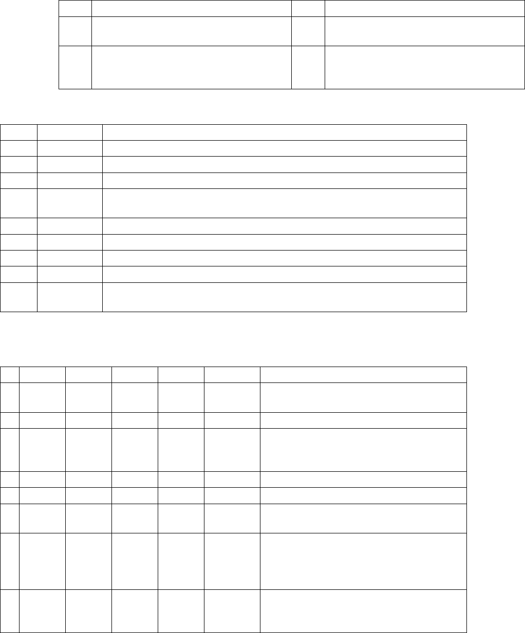
8.5.1.3 Base Adapter for CPx heads (for SX1/2)
The Base Adapter PCB (Part Number 03055516-xx) has the same purpose as the Head Adapter that is
used on the X series machines. It is used on the SX machines with both the CP20 and CPP heads.
1. Switch S1
2. H1 – H2 (Head)
3. H3 – H9 (Power Failure)
4. H10 – H11 (HCU)
5. 7 segment display
6. DIP switch block S2.
7. X4 - X14 – X15 connectors for the HCU.
8. X1 – X2 ribbon cables to the head.
9. X8 Service connector for checking voltages
10. X3 connector to the head interface C700.
Single Core Solution (SCS)
8.5.1.4 Single Core Solution (SCS)
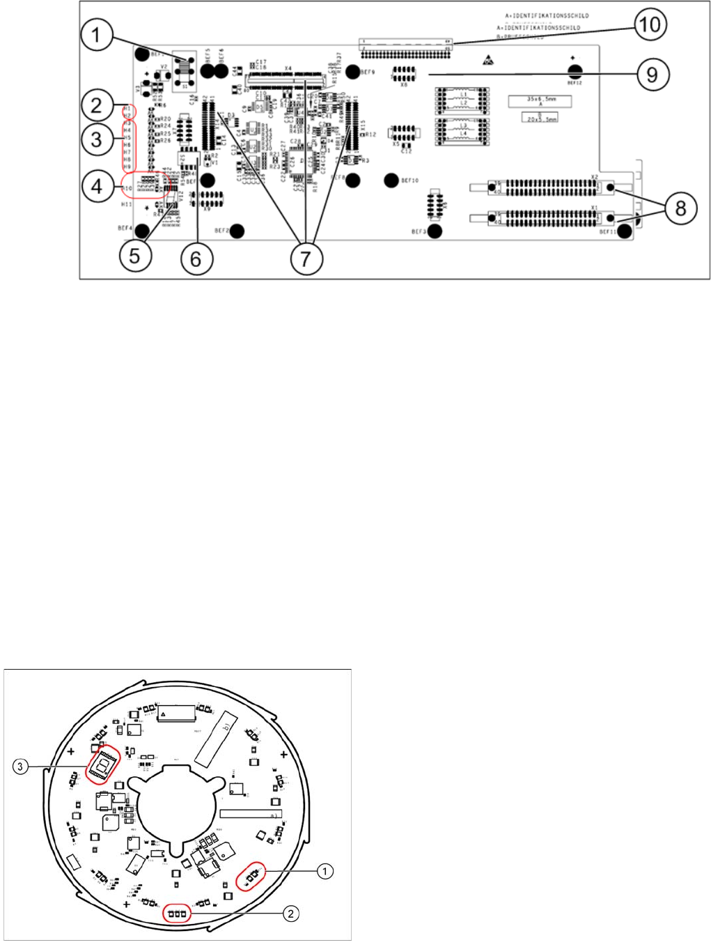
The SCS consists of two boards: the power module and the control module.
Power Module
The 7 segment display (3) provides information about the processor status.
Legend
1. Two LEDs for the status of each DP drive
2. Three LEDs for the operating voltages
3. 7 segment display for the processor status
The status of each DP drive is shown by two LEDs
(green, red) (1). Three further LEDs (2) show the
operating voltages:
▪ Input voltage P24 – 24 V
▪ Internal voltage DC/DC converter Vcc – 2.5 V
▪ Internal voltage DC/DC converter Vcc3 – 2.5 V