00194614-08 Trainingsdoku. SG X-Serie_X4i SW70x (AL2)_EN.pdf - 第125页
Communication and Control One Wire Bus One Wire Bus - Structure 125 Student Guide SIPLACE X-Serie and X4I SW70x (AL2) One Wire Bus in the SIPLACE X 4.5.1.2 One Wire Bus in the SIPLACE X Overview of one wire subsystems e.…
Communication and Control
One Wire Bus - Structure One Wire Bus
Student Guide SIPLACE X-Serie and X4I SW70x (AL2) 124
Basic Structure
4.5.1.1 Basic Structure
One wire bus principle
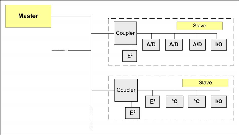
The one wire bus system consists in principle of a master with EEPROM (control unit), which controls
the various submodules such as A/D converters, EEPROM, temperature and I/O modules. Each
communication branch is equipped with an upstream coupler, which opens the branch for data transfer..
Communication and Control
One Wire Bus One Wire Bus - Structure
125 Student Guide SIPLACE X-Serie and X4I SW70x (AL2)
One Wire Bus in the SIPLACE X
4.5.1.2 One Wire Bus in the SIPLACE X
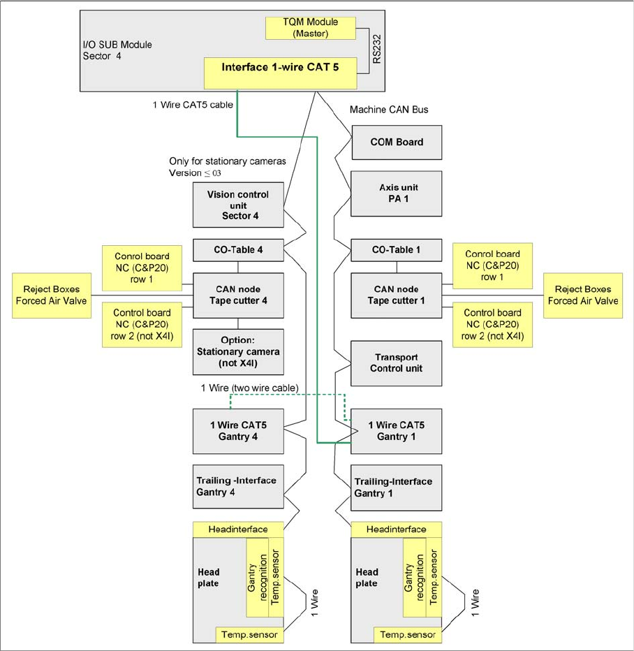
Overview of one wire subsystems e.g. PA1 on the SIPLACE X4I
In the SIPLACE X4I machine, the one wire bus is integrated via a separate CAT5 cable, which leads
from the main or subdistributor up to the trailing interface. The one wire bus is run through the trailing
cable from the trailing interface up to the head interface. This means that the cable structure is different
and only the temperature sensors are still monitored. The temperature values are used to calculate the
relevant offset values for placement accuracy.
Function Description
4.5.1.3 Function Description
When the machine is switched on, each one wire bus is assigned a fixed CAN ID.
One wire in PA1 --> CAN ID: 07d0
One wire in PA2 --> CAN ID: 07c0
During initialization of the bus system, each station registers with the master, after which the bus is ready
for operation.
In the non operative mode, the voltage level is 5 V on the one wire bus.
Communication and Control
One Wire Bus - Structure One Wire Bus
Student Guide SIPLACE X-Serie and X4I SW70x (AL2) 126
A repeat initialization can be performed with the CACCIA tool (see Function Control and Troubleshooting
for Service Work).
One Wire Bus Components
4.5.1.4 One Wire Bus Components
Assemblies:
1. Interface 1-Wire CAT5 on the SUB/MAIN module
2. 1 wire CAT 5 Gantry on the trailing interface (board between CAN bus and trailing interface)
3. 1 set of temperature sensors (replacement only as a set, due to serial number)
4. EEPROM for gantry recognition
Interface 1-Wire CAT5
Interface 1-Wire CAT5
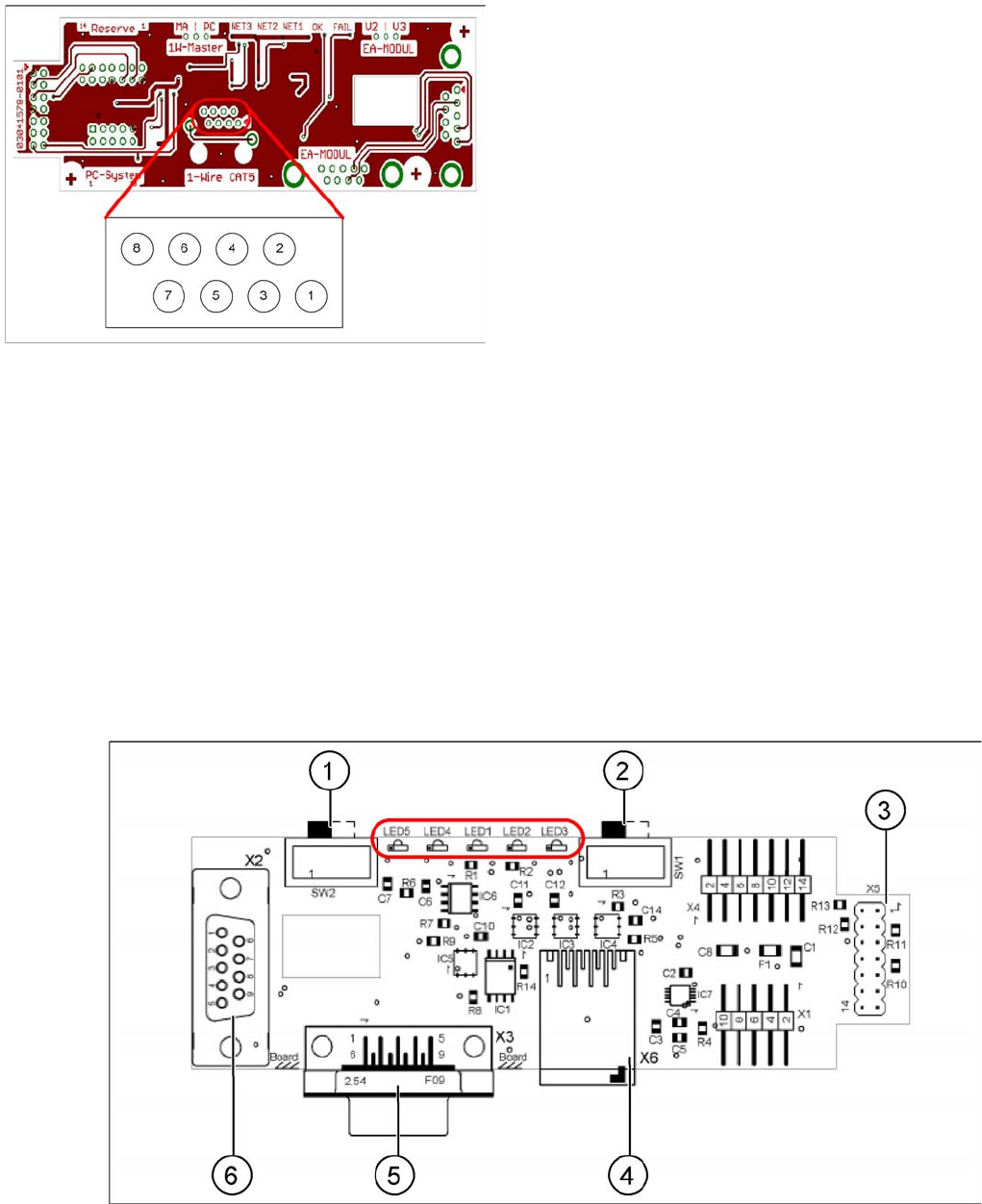
Interface 1-Wire CAT5 on the SUB/MAIN module (version 02) [03041578-01]
Interface 1-Wire CAT5
Legend
1. NC row 1 gantry 1/3
2. NC row 2 gantry 1/3
3. Temperature sensors gantry 1
4. Temperature sensors gantry 4
5. NC row 1 gantry 2/4
6. NC row 2 gantry 2/4
7. 24 V
8. GND
For initial analysis, the 5 V level can be measured at the
1-Wire-CAT5 connector of the interface.
The 24 V at pin 8 can be measured at the old 1-Wire and
serves as voltage supply for the nozzle changers. The
24 V are fed into the 1-Wire distributor. However, this is
not used at the interface.