4OM-1603-007_w.pdf - 第112页
4OM-1603 1-57 4. Maintenance Method : Chap.1 4.4 Method of Blow air • Remove dust and dirt etc. Remove slight dust and dirt by blow air or wiping off. Clean the tapered area of the vacuum nozzle with a lens cleaning clot…
4OM-1603
1-56
4. Maintenance Method : Chap.1
1202-002
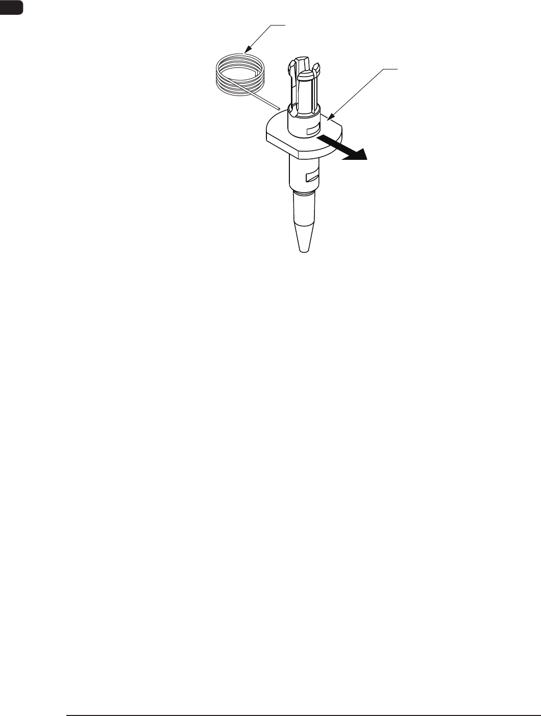
4.3 Nozzle Filter Removal Procedure
Push out the nozzle lter using the lter removal jig as shown in the following
gure.
Filter Removing Jig
Vacuum Nozzle
Push
Pushing out the nozzle filter.
F4A39-3
4OM-1603
1-57
4. Maintenance Method : Chap.1
4.4 Method of Blow air
•
Remove dust and dirt etc.
Remove slight dust and dirt by blow air or wiping off.
Clean the tapered area of the vacuum nozzle with a lens cleaning cloth.
Notice
Use clean, dry, and non-lubricated air for blow air.
F4A39-14
NOTICE
Blow air to the head when blow air to the nozzle.
There is a possibility that the clamp jaw breaks when
the air blow is done from the direction of the clamp
jaw to the nozzle.
1202-001
4OM-1603
1-58
4. Maintenance Method : Chap.1
1202-001
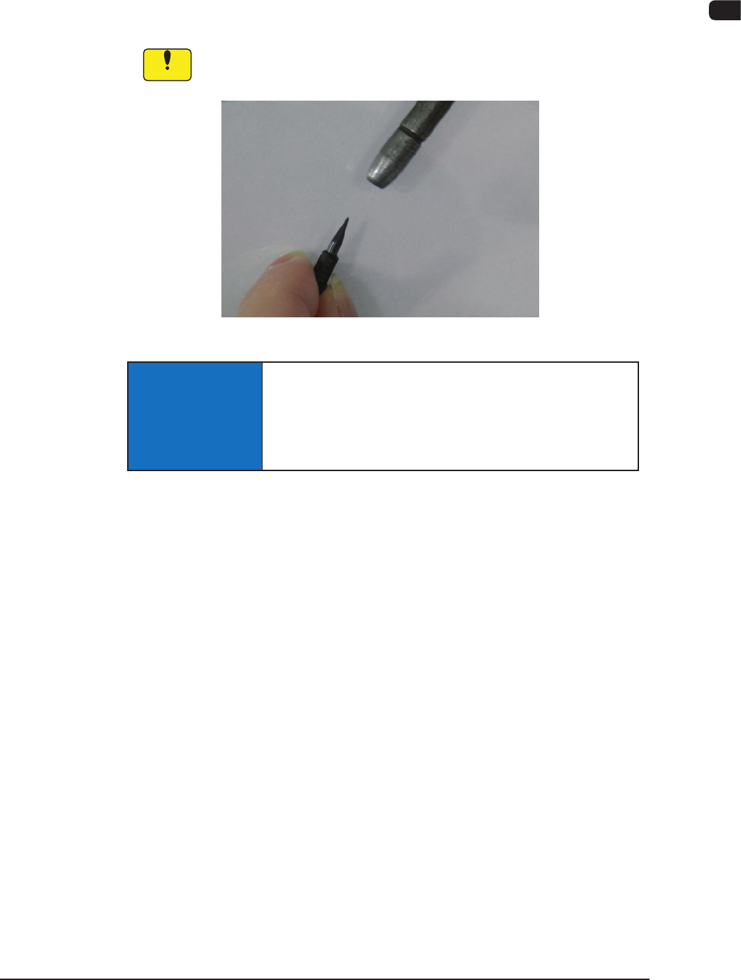
4.5 Cleaning of high-speed nozzle hole part with pin gauge
After the ultrasonic cleaning, conrm the clog of the nozzle hole with the
magnifying glass.
When the clog is conrmed, clean it with the pin gauge.
•
Select pin gauge
The pin gauge used is different depending on the kind of a high-speed nozzle.
Please select it referring to the combination shown next.
Unit : mm
Nozzle ID
Diameter
(center hole
diameter)
Diameter
(minimum hole
diameter)
Pin gauge
size
Direction of pin gauge
insertion
HG22C
f
0.1
f
0.08
f
0.06 Nail side, Head side
HG33C
f
0.2
f
0.08
f
0.07 Nail side, Head side
HG52C
f
0.4
f
0.25
f
0.2 Nail side, Head side
HG82C
f
0.7
f
0.35
f
0.3 Head side
HV82C
f
0.7
f
0.35
f
0.3 Nail side, Head side
HG13C
f
0.9
f
0.9
f
0.6 Head side
HV13C
f
0.9
f
0.9
f
0.6 Nail side, Head side
HG14C
f
1.1
f
1.1
f
0.8 Head side
HV14C
f
1.1
f
1.1
f
0.8 Nail side, Head side
HG15C
f
2.0
f
1.1
f
0.8 Head side
HV15C
f
2.0
f
1.1
f
0.8 Nail side, Head side
T4A15-1
•
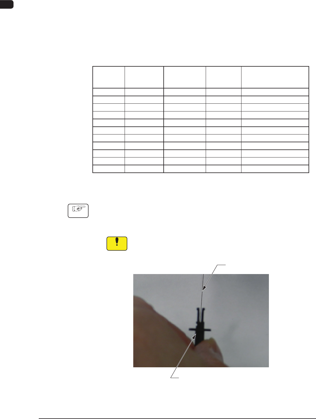
Method of cleaning high-speed nozzle hole
Procedure
(1) Firmly have the high-speed nozzle as shown in the following photograph
and insert it while matching a pin gauge center axis to a center axis of
a high-speed nozzle.
Notice
When a center axis shifts, the head might be damaged.
Pin gauge
High-speed nozzle
F4A39-15