4OM-1603-007_w.pdf - 第125页
4OM-1603 1-70 6. Head Change Procedure (Hard) : Chap.1 1202-002 6.2 Required Material List for T eaching and Precision Adjustment (At the time of Head Change) Product Item Part No. Q'ty T raching Precision Adjustmen…
4OM-1603
1-69
6. Head Change Procedure (Hard) : Chap.1
1202-002
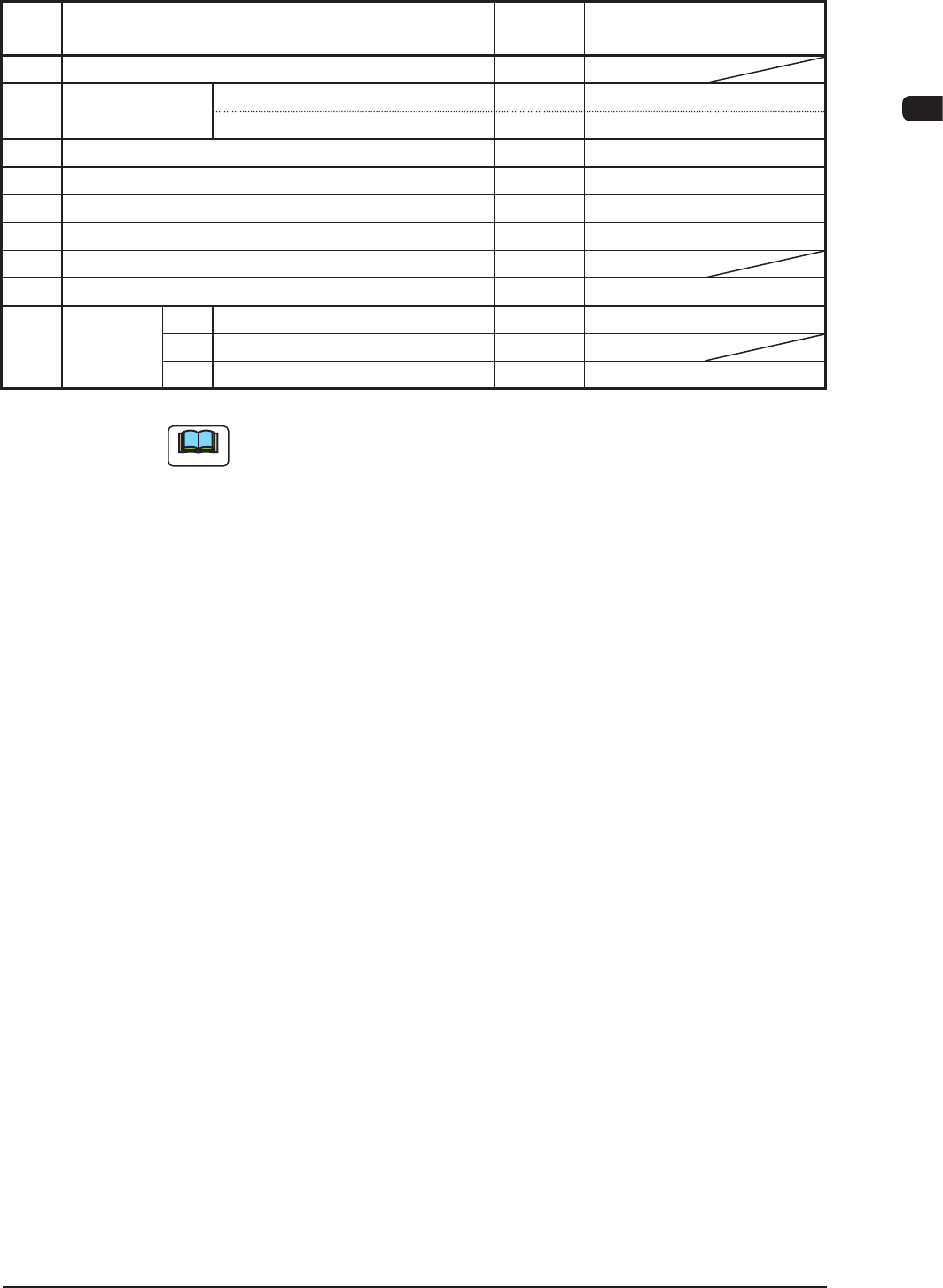
6.1 Re-Teaching Items in Head Change
Work
Priority
Teaching Item
Teaching
Type
High Speed
Head
Multi-Function
Head
1
NL-Axis Origin / Master Nozzle Level Automatic
○
2
Chute Level (At the time of shipping) Automatic
(At the time of head change) Automatic
○ ○
3
PEC Recognition Camera & Beam Automatic
○ ○
4
Component Recognition Camera Position Automatic
○ ○
5
Head Rotational Angle Axis Automatic
○ ○
6
Head Rotational Center / Reference Mark Position Automatic
○ ○
7
Fly Recognition Camera Automatic
○
8
Nozzle Inclination Automatic
○
9
Precision
Adjustment
①
Head Offset (A) Manual
○
②
Head Offset (ΔA), (B) Manual
○
③
Head Offset (B) For Each Angle Manual
○
T4A16
Note
(a) For the teaching items, perform each of them in the order of precedence.
(b) When any of the heads is changed from the high-speed head to the multi-
functional head, perform the steps "6", "7" and "8" also for unchanged
high-speed heads.

4OM-1603
1-70
6. Head Change Procedure (Hard) : Chap.1
1202-002
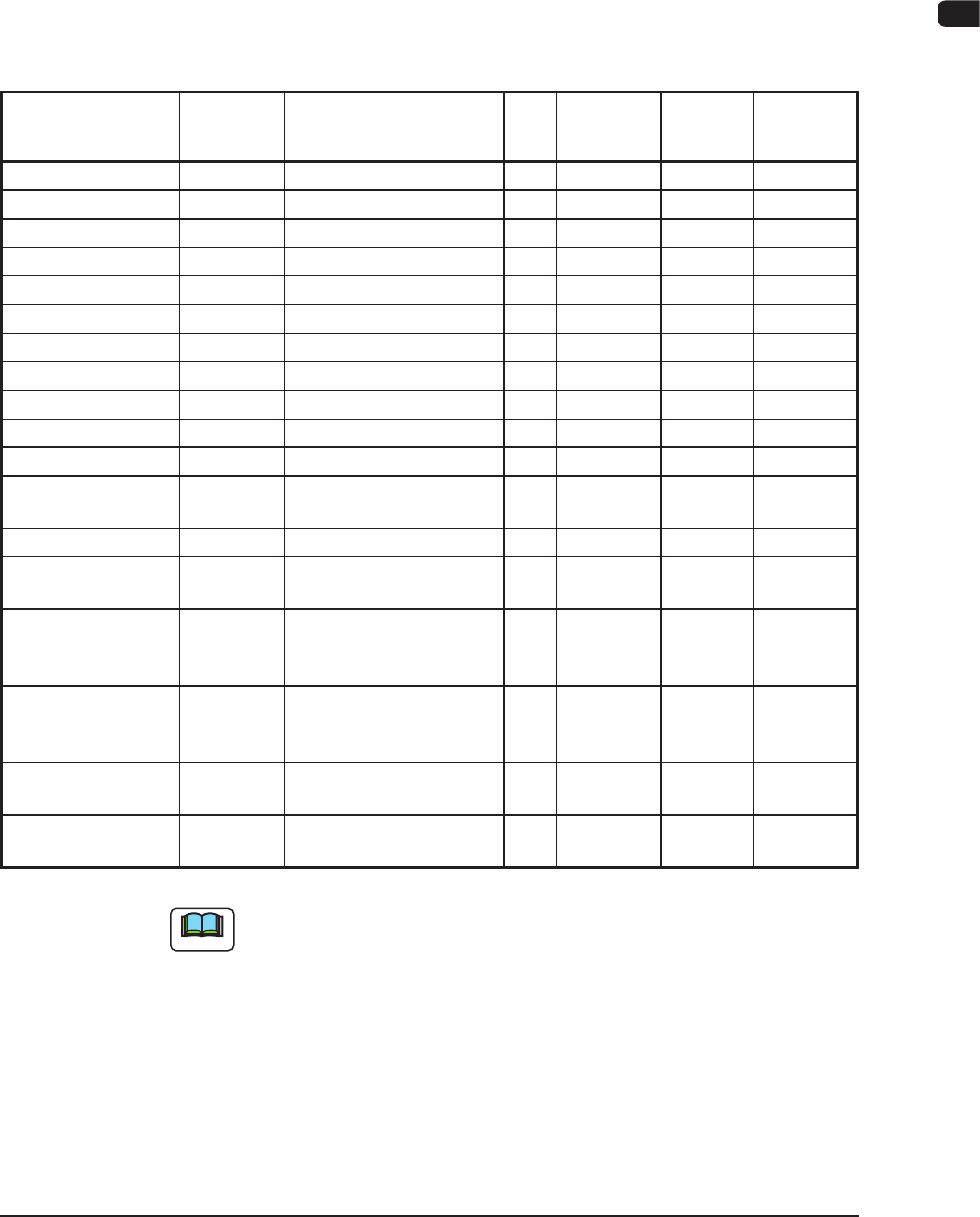
6.2 Required Material List for Teaching and Precision
Adjustment (At the time of Head Change)
Product Item Part No. Q'ty Traching
Precision
Adjustment
Common
1 BARON 1
○
2 BARON Glass PCB 1
○
3 Adhesive Double Coated Tape 1
○
4 Offset Calculation Sheet 1
○
High-Speed Head Adjustment (For Single Head Mode)
1 0603 Master Chip Component 0914J10A 1
○
2 QFP Glass Jig 211D9639 1
○
3 GD28081 Feeder 1
○
4 HA09 Nozzle 1
○
5 HG31 Nozzle 15
○
6 Master Nozzle 1
○
Multi-Function Head Adjustment (In the Use of Feeder Cart)
1 QFP Glass Jig 8
○ ○
2 Jig Placement Plate 1
○
3 Jig Bracket (1) 1
○
4 Jig Bracket (2) 1
○
5 M3×10 Sems Screw 4
○
6 FA04 Nozzle 1(3)
○
7 FF01 Nozzle 1(3)
○ ○
T4A18
4OM-1603
1-71
7. Consumables and Servicing Parts : Chap.1
1202-007
7. Consumables and Servicing Parts
7.1 List of Consumables
This component list is for the components that would be worn within one year.
When any of these components are to be purchased, contact Marketing Dept. of
HITACHI High-Technologies or our sales agent.
Product Name Part No. Part Name Q'ty
Recommended
number per year
note (a)
Exploded
Illustration
Remarks
Nozzle (HV81C) HV81C--- ASSY, NOZZLE (HV81C) 30 30
Nozzle (HV03C) HV03C--- ASSY, NOZZLE (HV03C) 30 30
Nozzle (HB03C) HB03C--- ASSY, NOZZLE (HB03C) 30 30
Nozzle (HB04C) HB04C--- ASSY, NOZZLE (HB04C) 30 30
Nozzle (HA04C) HA04C--- ASSY, NOZZLE (HA04C) 30 30
Nozzle (HA05C) HA05C--- ASSY, NOZZLE (HA05C) 30 30
Nozzle (HA09C) HA09C--- ASSY, NOZZLE (HA09C) 30 30
Nozzle (PA05C) PA05C--- ASSY, NOZZLE (PA05C) 30 30
Nozzle (HG31C) HG31C--- ASSY, NOZZLE (HG31C) 30 30
Nozzle (HG51C) HG51C--- ASSY, NOZZLE (HG51C) 30 30
Nozzle (HG21C) HG21C--- ASSY, NOZZLE (HG21C) 30 30
Vacuum Filter 225B0572 AIR LINE EQPT 60 240 Fig. G1-5,
Fig. O1-1
Fluorine Sheet 212A2743 GUIDE 2 2 Fig. C2-1
Urethane Clamp
ASSY
0920715E
09207152
Sliding Type Clamper ASSY
Fixed Type Clamper ASSY
2
2
2
2
Fig. C2-5
Seal ASSY
Flat Ring
Set Bolt
0920715E
0920H159
0920H158
SEAL
Screw 01605B0
2
2
12
2
2
12
Fig. C2-6 Cutter Unit
Sliding Side
For the Roller
DISK ASSY
Cutter Blade
Cutter Blade Set Bolt
0920716D
0920H127
221A0231
DISK
BOLT, HEX-SCT
4
4
12
4
4
12
Fig. C2-6 Note (c)
Nozzle Filter 225A0045 Nozzle Filter 30
(15)
960
(480)
Fig. D1-1 Note (d)
Vacuum Filter 630 069
5816
AIR LIN EQPT 3 18 Fig. D1-1 Note (d)
T4A16
Note
(a) The recommended number of pieces is the value for reference only.
(b) Refer to "3. Maintenance Spots" for component replacement procedures.
(c) For the cutter blade replacement, consult with our service personnel
because it is a dangerous procedure.
When the cutter blade is replaced, also replace the bolt.
(d) The gures in brackets are applied for the multi-functional head.