4OM-1603-007_w.pdf - 第122页
4OM-1603 1-67 6. Head Change Procedure (Hard) : Chap.1 1202-002 (8) Hold the head bumper and handle section (for the head without the handle, hold the bottom of the control box), and move the head up to remove. Note For …
4OM-1603
1-66
6. Head Change Procedure (Hard) : Chap.1
1202-002
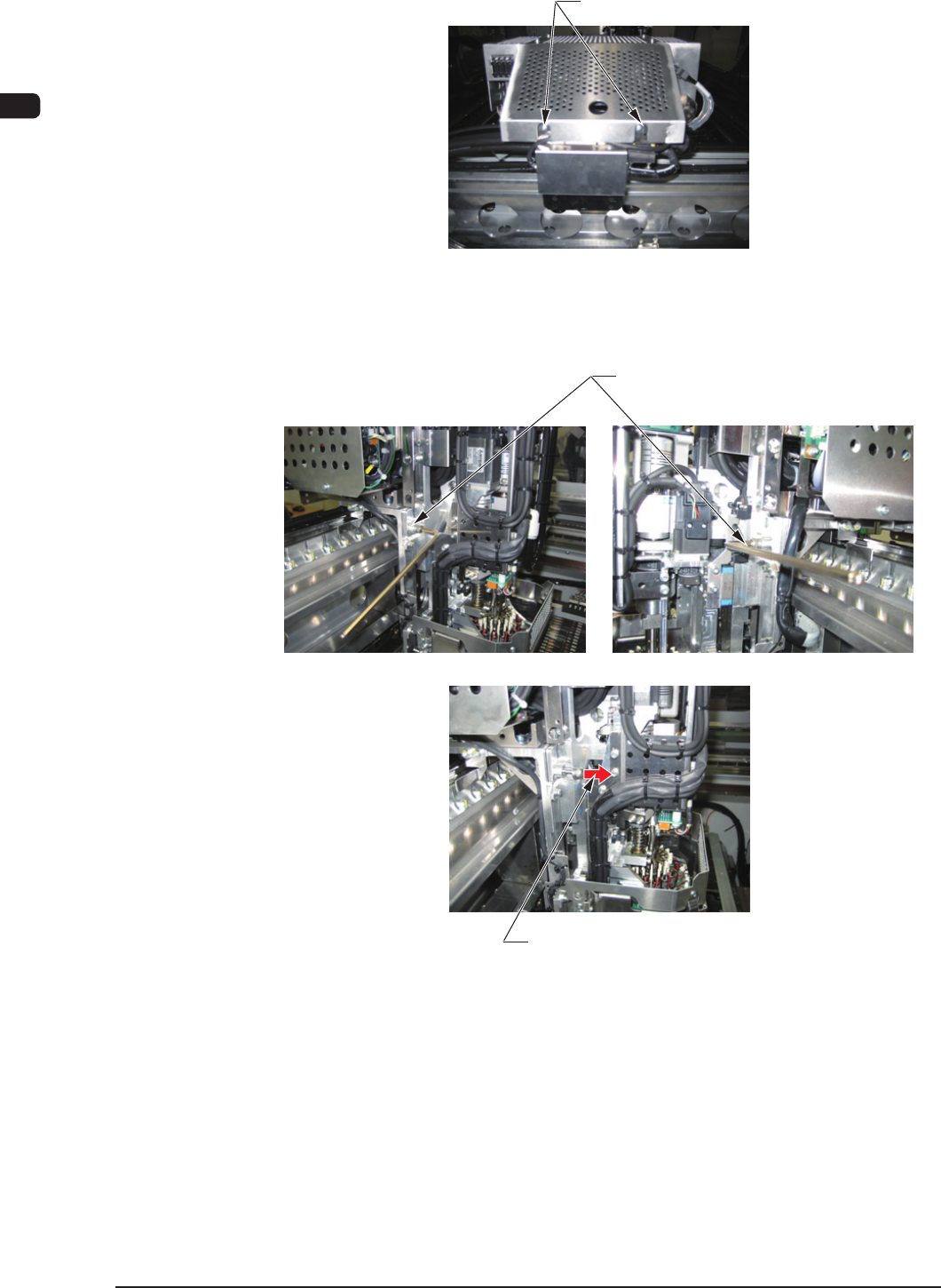
(6) Loosen the round head screws on the rear of the control box.
Round Head Screw
F4A45
(7) Loosen the head set bolt (M6 bolt) and pull out the bolt.
Head Set Bolts
Pull out the head set bolt.
F4A46
4OM-1603
1-67
6. Head Change Procedure (Hard) : Chap.1
1202-002
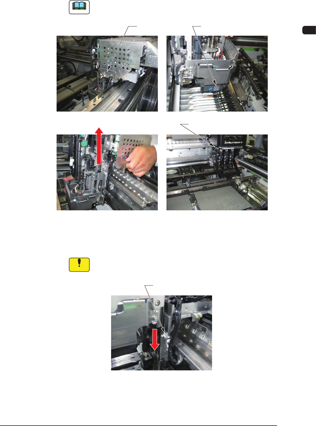
(8) Hold the head bumper and handle section (for the head without the handle,
hold the bottom of the control box), and move the head up to remove.
Note
For the multi-functional head, hold the bottom of the control box instead
of the handle to perform the work.
Handgrip Bumper
Multi-Function Head Bumper
Move it up
F4A47
(9) Insert the head to be attached to the head attachment rail, from the beam
upper direction, and move it down slowly to the lower wedge position.
Notice
Take care not to drop the head when the above work is performed.
Head Attachment Rail
F4A48
4OM-1603
1-68
6. Head Change Procedure (Hard) : Chap.1
1202-002
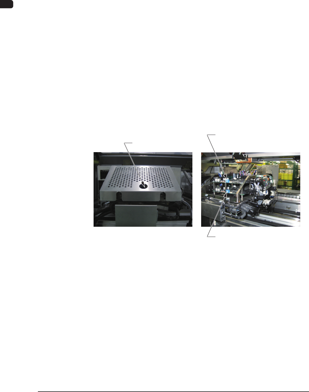
(10) Push the head against the unit lower section.
(11) Fasten the head set bolts M6.
(12) Fasten the round head screws on the rear of the control box.
(13) Connect the connector.
(14) Connect the piping tubes.
(15) Connect the ber optic cables to the multi-axis board.
(16) Set up the rotary switch.
High Speed Head (Rear Side) : 0
High Speed Head (Front Side) : 1
Multi-Function Head (Rear Side) Upper Board : 0
Multi-Function Head (Rear Side) Lower Board : 2
Multi-Function Head (Front Side) Upper Board : 1
Multi-Function Head (Front Side) Lower Board : 3
Rotary Switch
Multi-Function Head (Upper Board)
Rotary Switch
Multi-Function Head (Lower Board)
Rotary Switch
F4A49
(17) Turn the air switch to the supply side and turn on the power to the machine.