4OM-1603-007_w.pdf - 第128页
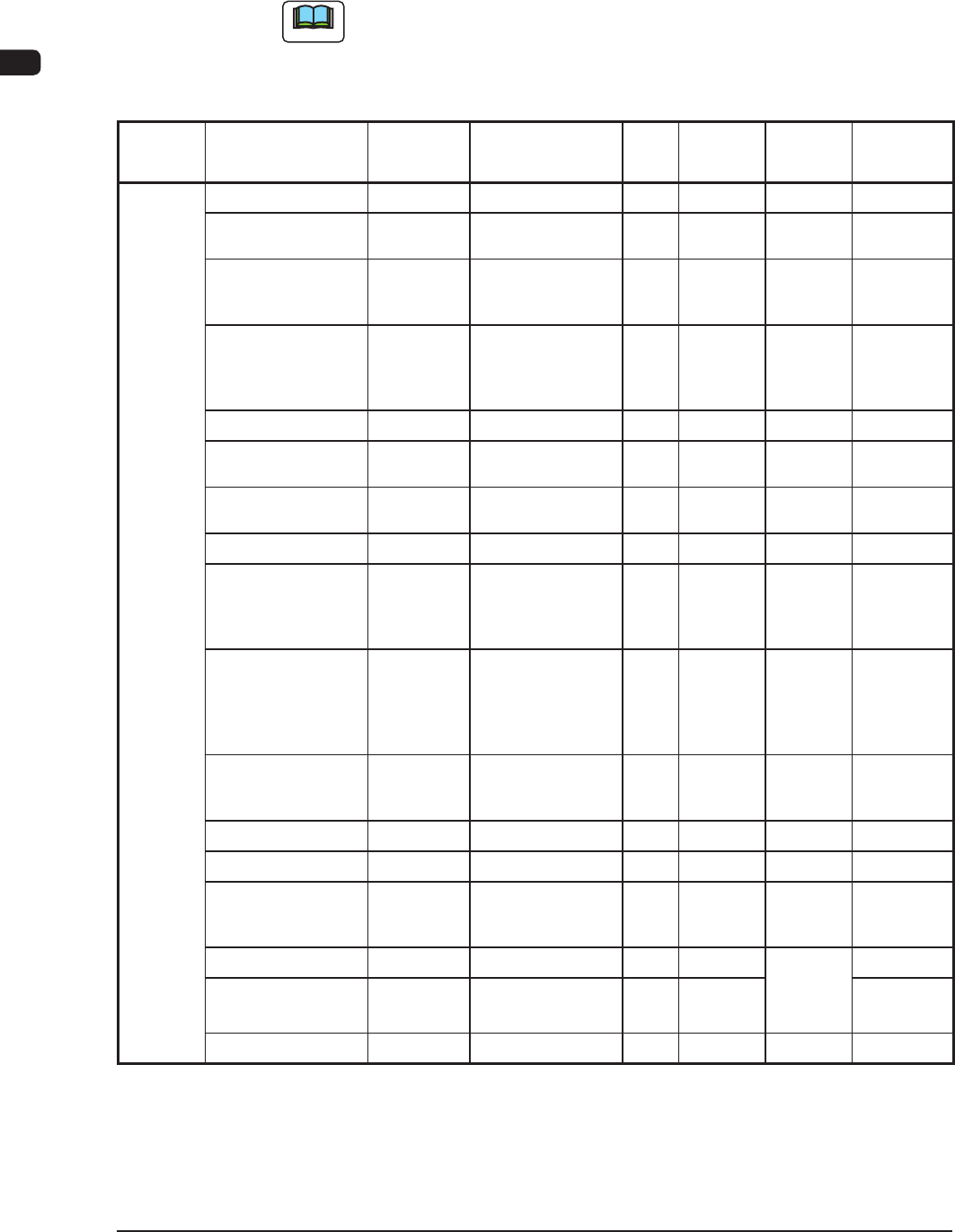
4OM-1603 1-73 7. Consumables and Servicing Parts : Chap.1 Block Name Product Name Part No. Part Name Q'ty Recommended # of years Note(a) Exploded Illustration Remarks Main Unit T ouch Panel (Both Sides) 4U210135 EQU…
4OM-1603
1-72
7. Consumables and Servicing Parts : Chap.1
7.2 List of Servicing Parts
This component list is for the components for which maintenance is required in
several years, for your reference.
Note
For the maintenance procedure for the important maintenance components,
consult with our service personnel because high skill is required for such
maintenance.
Block
Name
Product Name Part No. Part Name Q'ty
Recommended
# of years
Note(a)
Exploded
Illustration
Remarks
Head
Section
Solenoid Valve 23D10016 ACCESSORY,SV 30 3 Fig. G1-5
Nozzle Shaft ASSY 09163KOK
ASSY,GUIDE,LINEAR
30
Sets
- Fig. G1-5 Note (c)
Hexagon Socket
Head Cap Screw
M2×4
221AA121 BOLT,HEX-SCT 30 - Fig. G1-5 For Nozzle
Shaft Setup
Note (b)
O-Ring for Seal
Holder
226A0286
(SO-008-13)
0916D31E
(SO-010-12)
SEAL 30
90
2 Fig. G1-5
Nozzle Shaft Spring 0916DK2D SPRING,COMP 30 2 Fig. G1-5
Packing for Nozzle
DYR-2.5 Custom
226A0279 SEAL 60 - Fig. G1-5
O-Ring for Filter
SO-009-5A
0916D338 SEAL 60 2 Fig. G1-5
Line Sensor 23G00313 SENSOR,PELEC 2 2 Fig. G1-5
Diffusion Plate
(Outside)
213D1169
(*1)
0916D31G
(*2)
DISK 2 - Fig. G1-5 Note (c)
Diffusion Plate
(Inside)
213D1336
(*1)
0916D31F
(*2)
DISK 2 - Fig. G1-5 Note (c)
Hexagon Socket
Head Cap Screw
M1.6×4
221AA332 BOLT,HEX-SCT 14 - Fig. G1-5 For Diffusion
Plate Setup
Note (b)
Top Block 211G6373 BLOCK 30 - Fig. G1-5
Cam Follower (f2.5) 222H0163 CAMFOLLOWER 30 - Fig. G1-5
Hexagon Socket
Head Cap Screw
M1.6×3
221AA330 BOLT,HEX-SCT 60 - Fig. G1-5 For Top
Block Setup
Note (b)
Sensor PM-U24 23G20046 SENSOR,PHOTO 2 3 Fig. G1-3,
Fig. G1-4,
Fig. G1-5,
Fig. G1-6
Sensor PM-L24 23G10059 SENSOR,PHOTO 10 3
Slip Ring 0916D30T SLIP RING 2 2 Fig. G1-6
T4A17
1202-006
4OM-1603
1-73
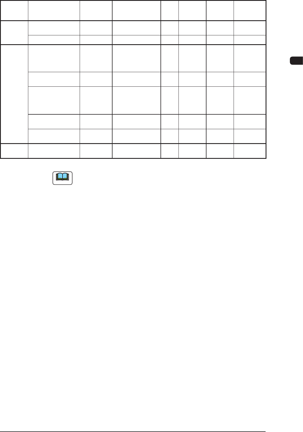
7. Consumables and Servicing Parts : Chap.1
Block
Name
Product Name Part No. Part Name Q'ty
Recommended
# of years
Note(a)
Exploded
Illustration
Remarks
Main Unit Touch Panel
(Both Sides)
4U210135 EQUIPMENT 1 3 Fig. F1-3
Vacuum Pump 0914B10H VACUUM,PUMP 1 - Fig. D5-2
Transfer
Unit
Transfer Pully 223Q0663 PULLEY,TIMING 12 5 Fig. H1-8,
Fig. H1-9,
Fig. H1-10,
Fig. H1-11
Transfer Pully 223Q0755 PULLEY,TIMING 2 5 Fig. H1-6,
Fig. H1-7
Transfer Pully 223M0059 PULLEY,TIMING 10 5 Fig. H1-6,
Fig. H1-7,
Fig. H1-8,
Fig. H1-10
Transfer Belt 223L0383 BELT,TIMING 2 3 Fig. H1-6,
Fig. H1-7
Transfer Belt 223L0384 BELT,TIMING 4 3 Fig. H1-8,
Fig. H1-10
Cutter
Section
Cutter Block ASSY 092071IW Cutter Block ASSY 2 2 -
T4A18
Note
(a) The recommended year of pieces is the value for reference only.
(b) Do not reuse any bolt removed during maintenance.
1202-006

4OM-1603
1-74
7. Consumables and Servicing Parts : Chap.1
1202-002