2OM-1064-002.pdf - 第11页
2. Hierarchical Structure of Data Edit Menus Data editing is described along with the following hierarchical structure. The numbers in ( ) show item Nos. to be referred to. Pattern Program Component Library Data Device D…
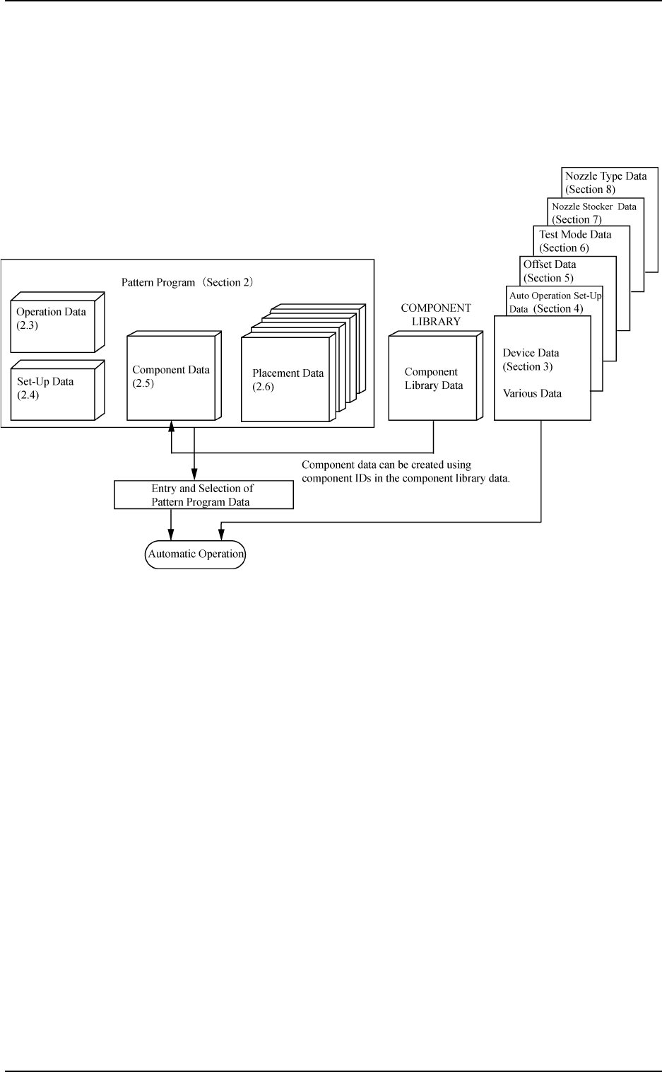
1. Scope and Description of Each Data
To place components with this machine
It is required to create and edit pattern program data (operation data, set-up
data, component data, and placement data), component library data, and vari-
ous data (device data, auto operation set-up, etc.).
1. Scope and Description of Each Data
9910-001 1-2 Tg0247-PM-PM
Fig. 1.1
Pattern Program
Operation Data : This data is used to generally manage pattern program data.
P.C.B. size, pattern program offset, etc., can be set.
Set-Up Data : This data is used to determine whether or not the conveyor
width should be set up automatically.
Component Data : This data is used to set parameters which determine a type
(ID) of component to be allocated to each feeder slot No.
(FDR No.).
Placement Data : This data is used to set parameters which select compo-
nents (FDR No.) and determine coordinates and directions
of components to be placed on a production P.C.B.
Component Library Data
This information data is used to pick up, recognize, and place each component.
Included in this library data are types and sizes of components, package types,
placement speed, etc.
Various Data
Device Data, Auto Operation Set-Up, Offset Data, Test Mode, Nozzle Stocker
Data, and Nozzle Type Data
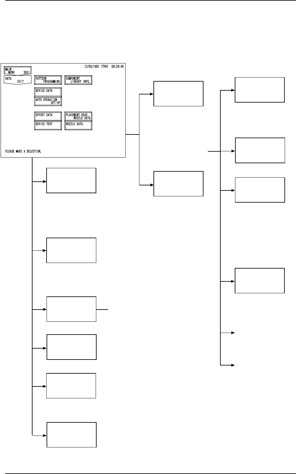
2. Hierarchical Structure of Data Edit Menus
Data editing is described along with the following hierarchical structure.
The numbers in ( ) show item Nos. to be referred to.
Pattern Program
Component
Library Data
Device Data
(Section 3)
Operation Data
Placement Data
• P.C.B. TRANSFER MODE SET-UP
• MACHINE COMMUNICATION
ADDRESS SET-UP
• TRAY MATRIX MODE
Auto Operation
Set-Up
(P.E.C. MARK DATA EDIT)
(2.3.3 in Section 2)
Offset Data
Test Mode
Nozzle Stocker
Data
Nozzle Library
Info.
(2.3 in Section 2)
Component Data
• TAPE A / B
• VIB. STICK A / B
• TRAY L / R
• PLACEMENT DATA (P) U01
• PLACEMENT DATA (O) U01
• PLACEMENT DATA (V) U01
(PLACE. DATA UNIT EDIT)
(4.7 in Section 2)
(USED NOZZLE
INFORMATION)
(2.1.3 in Section 2)
(Section 4)
• PU CORR/MAINT CY ALM
• RECOG ERR IMAGE SAVE SET-UP
• AUTOMATIC TUNING
(Section 5)
(Section 6)
• DEVICE OFFSET
• FEEDER (A) OFFSET
• FEEDER (B) OFFSET
• HEAD MASTER OFFSET
• HEAD OFFSET
• HEAD CENTER OFFSET
• NOZZLE STOCKER OFFSET
• CAMERA REFERENCE GAIN/LEVEL
• COMP. RECOG CAMERA OFFSET
• P.E.C. RECOG CAMERA OFFSET
• COMP. RECOG BRIGHTNESS
• OFFSET TEACHING BRIGHTNESS
• ROOM TEMPERATURE AT LTG TEACHING
• TRAY FEEDER OFFSET
• COMPONENT REJECT OFFSET
• OFFSET TEACH
• HEAD OFFSET (GET BOTH IMAGE)
• V. BEND DETECTION (Option)
(Section 7)
(Section 8)
• NOZZLE ID LIST
• DELETE NOZZLE
• SEARCH NOZZLE
• DATA EDIT
(Section 2)
(COMPONENT LI-
BRARY)
• PROGRAM CHANGE
• PROGRAM CHECK
• PROGRAM DELETE
• USED NOZZLE
INFORMATION
• PROGRAM EDIT
• DELETE COMPONENT
• SEARCH COMPONENT
• EDIT DATA
(2.4 in Section 2)
(2.5 in Section 2)
(2.6 in Section 2)
Set-Up Data
2. Hierarchical Structure of Data Edit Menus
9910-001 1-3 Tg0247-PM-PM

0004-001 1-4 Tg0247-PM-PM