2OM-1064-002.pdf - 第161页
Fig. 3.8 TRA Y MA TRIX MODE Set “X DIR.” or “Y DIR.” (direction in which components should be taken out) in this data box. In normal cases, “Y DIR.” should be selected. Fig. 3.9 shows the order (arrow directions) in whic…
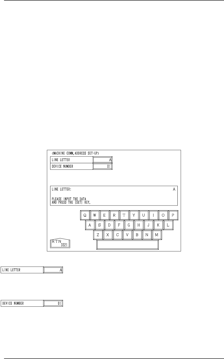
Fig. 3.7
LINE LETTER
Set a line letter (interface address to the programming device
(option)) in the component placement system.
• Data Input Range: A to Z (Internal Data: ASCII)
DEVICE NUMBER
Set a device number in the component placement system line.
This data is used to identify the object machine when several
machines (same models) are assembled, forming one system
line.
(Interface Address to Programming Device)
• Data Input Range: 01 to 26 (Internal Data: ASCII “A to Z”)
3. MACHINE COMM. ADDRESS SET-UP Display
9910-001 3-12 Tg0247-PM-PM
3. MACHINE COMM. ADDRESS SET-UP Display
When data is exchanged between a machine and an external device such as a
programming device (option), it is required to specify the machine (line letter
and device No.).
*1 When a component placement system line is constructed, it is advisable
that a common line letter be used in one system (combination of input,
main, and output machines).
*2 “Device Number” is an address data used to identify the object machine
when there is another machine of the same type in the same line.
Notes: (a) When data is exchanged between the main machine and the pro-
gramming device (option), the same line letter must be entered on
the programming device side.
(b) Even if a machine address data is changed, machine operation
remains unchanged. However, if an address data is changed after
each offset data for the machine is stored in the programming
device, the offset data may not be reloaded to the machine.
When the [MACHINE COMM. ADDRESS SET-UP] key is pressed at the
“DEVICE DATA” display, the following display appears on the screen.
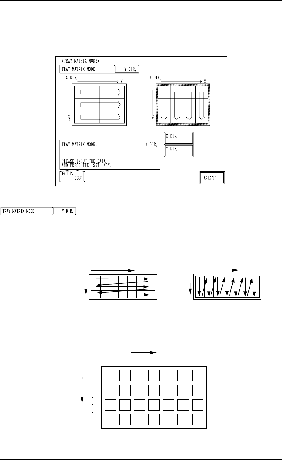
Fig. 3.8
TRAY MATRIX MODE
Set “X DIR.” or “Y DIR.” (direction in which components
should be taken out) in this data box.
In normal cases, “Y DIR.” should be selected.
Fig. 3.9 shows the order (arrow directions) in which compo-
nents are taken out.
4. TRAY MATRIX MODE Display (Option)
When the [TRAY MATRIX MODE] key is pressed at the “DEVICE DATA”
display, the following display appears on the screen.
4. TRAY MATRIX MODE Display (Option)
9910-001 3-13 Tg0247-PM-PM
{
: Component Existing
×
: No Component (Taken Out)
{{{
{{{{{
{{{{{
×
×××
×
×
×××
{{
{{
{{
Y
1
2
99
1
X
99
・
・・
・
・
・・
・
・
・・
・
・
・・
・
・
・・
・
・
・・
・
3
2
X
Selection of “X DIR.”
Y
X
Selection of “Y DIR.”
Y
Fig. 3.10
Fig. 3.9
Example: The tray is in the condition (in the middle of pro-
cess) shown in Fig. 3.10.
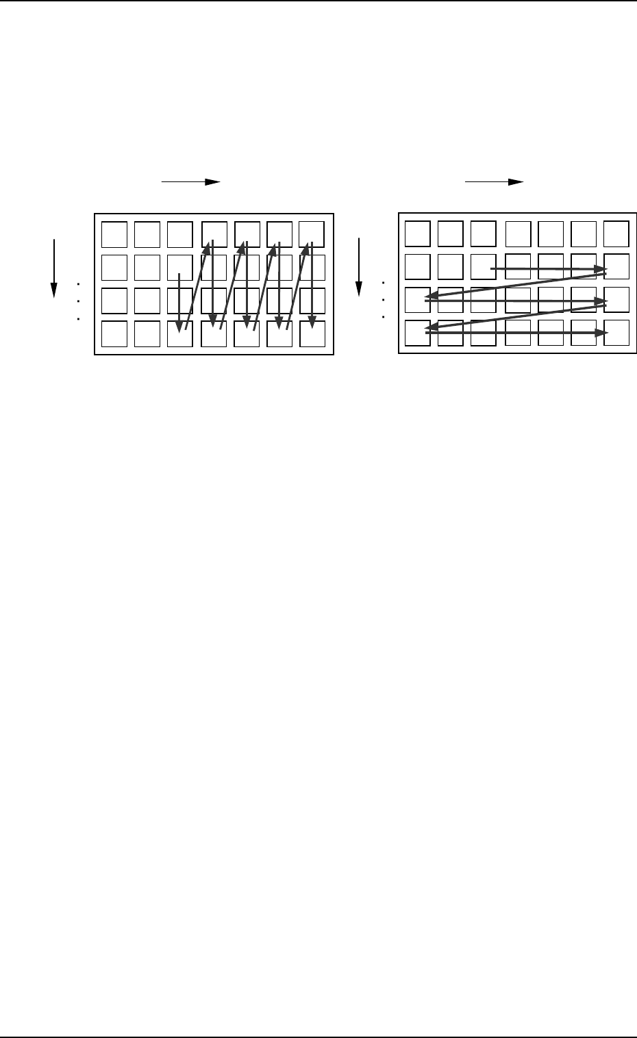
• The first component pick-up position is assumed to be “X:
3, Y: 2”.
z : Component Picked Normally
{ : Component Left Behind
Shadowed : Mispick
4. TRAY MATRIX MODE Display (Option)
z
z
z
zz
z{{
{{
z
zz
zz
zz
z
z
z
z z
z
z
z
z
z
z
z z z
z
z z
zz
z
z
Selection of “Y DIR.”
Selection of “X DIR.”
Y
1
2
99
1
X
99
・
・・
・
・
・・
・
・
・・
・
・
・・
・
・
・・
・
・
・・
・
3
2
1
X
99
・
・・
・
・
・・
・
・
・・
・
・
・・
・
・
・・
・
・
・・
・
3
2
Y
1
2
99
××
×××
××××
××
××× × ×××
Fig. 3.11-1 Fig. 3.11-2
9910-001 3-14 Tg0247-PM-PM