2OM-1064-002.pdf - 第98页
9910-001 2-86 Tg0247-PM-PM Placement Data (P) U02 3. Example of Pattern Program Creation Enter “0” (zero) in all data fields of the last step and “P” or “Q” as a control command. Fig. 2.68 Placement Data (O) U02 Enter “0…
3. Example of Pattern Program Creation
(2) Example of Data Creation
• Use the following placement data.
Placement Data (P) U01, (O) U01, and (V) U01
(P) U02, (O) U02, and (V) U02
(P) U03, (O) U03, and (V) U03
• P.E.C. recognition must be specified for each individual repetitive pat-
terns in the operation data.
Set “ON” in the “P.E.C. RECOGNITION” and “ON” in the “IMAGE”
data box of the label “P.E.C. RECOGNITION MODE”.
Note: Data for Model C must be created as repetitive pattern for one unit
P.C.B. because the P.E.C. recognition function (global) is implemented
according to the repetitive pattern program data created for a unit P.C.B.
Plecemnt Data (P) U01
9910-001 2-85 Tg0247-PM-PM
Enter “0” (zero) in all data fields of the last step and “P” or
“Q” as a control command.
Fig. 2.65
Plecemnt Data (O) U01
Enter “0” (zero) in all data fields of the last step and “E” as
a control command.
Fig. 2.66
Plecemnt Data (V) U01
Fig. 2.67
Notes: (a) The mark code Nos. registered in the “MARK DATA” data boxes
at the “OPERATION DATA” display must be entered in the “F1”
and “F2” data fields.
(b) V-0001, V-0002, V-0003 ... These Nos. correspond to the place-
ment steps.
Do not enter any parameter unless the marks at the placement
position for each individual components should be recognized.
P-NO. X(mm) Y(mm) Z(THETA) H(mm) FDR S V C COMMENT
0000 +0.00 +0.00 +0
°
00’ +0.00 000 - 02 -
0001 +5.00 +20.00 +0
°
00’ +0.00 101 - 00 -
0002 +15.00 +10.00 +180
°
00’ +0.00 201 - 00 -
0003 +25.00 +10.00 +90
°
00’ +0.00 301 - 00 -
0004 +0.00 +0.00 +0
°
00’ +0.00 000 - 00 P
O-NO. X(mm) Y(mm) Z(THETA) H(mm) C COMMENT
0000 +0.00 +0.00 +0
°
00’ +0.00 -
0001 +5.00 +5.00 +0
°
00’ +0.00 -
0002 +35.00 +5.00 +0
°
00’ +0.00 -
0003 +65.00 +5.00 +0
°
00’ +0.00 -
0004 +0.00 +0.00 +0
°
00’ +0.00 E
V-NO. V X1(mm) Y1(mm) F1 X1(mm) Y1(mm) F2 C
0000 02 +5.00 +5.00 01 +25.00 +25.00 01 -
0001 00 +0.00 +0.00 00 +0.00 +0.00 00 -
0002 00 +0.00 +0.00 00 +0.00 +0.00 00 -
0003 00 +0.00 +0.00 00 +0.00 +0.00 00 -
0004 00 +0.00 +0.00 00 +0.00 +0.00 00 P
9910-001 2-86 Tg0247-PM-PM
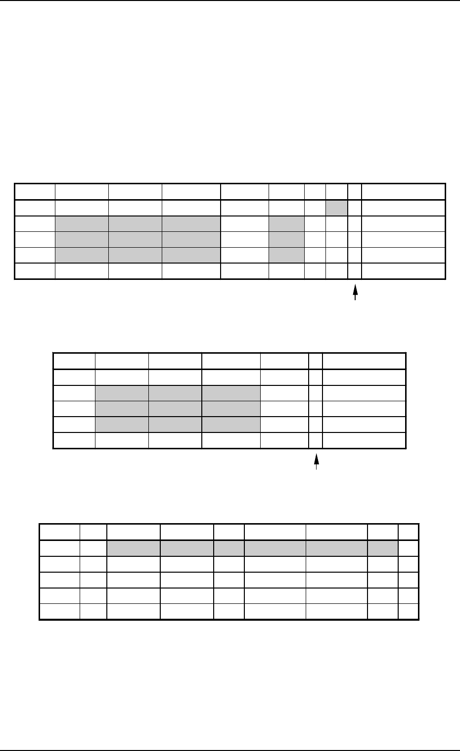
Placement Data (P) U02
3. Example of Pattern Program Creation
Enter “0” (zero) in all data fields of the last step and “P” or
“Q” as a control command.
Fig. 2.68
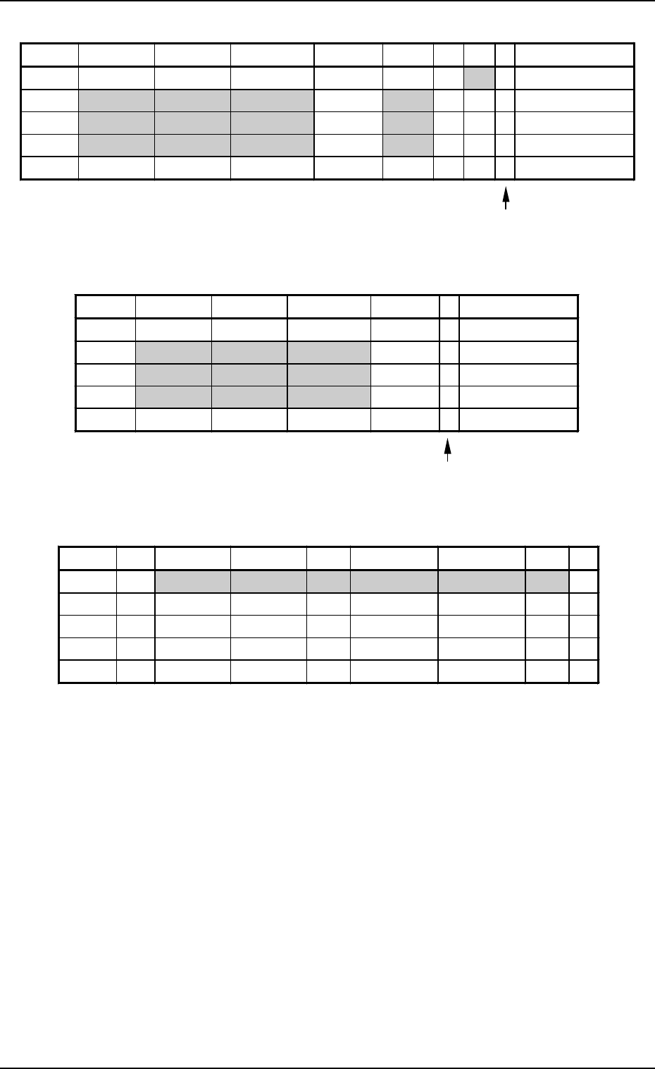
Placement Data (O) U02
Enter “0” (zero) in all data fields of the last step and “E” as
a control command.
Fig. 2.69
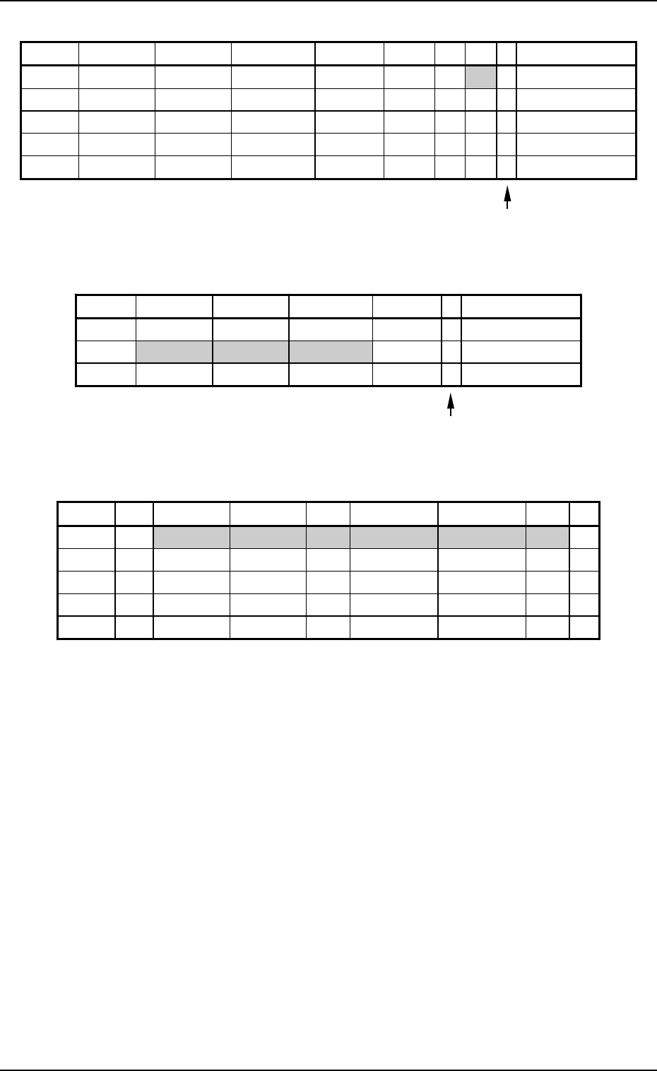
Placement Data (V) U02
Fig. 2.70
Notes: (a) The mark code Nos. registered in the “MARK DATA” data boxes
at the “OPERATION DATA” display must be entered in the “F1”
and “F2” data fields.
(b) V-0001, V-0002, V-0003 ... These Nos. correspond to the place-
ment steps.
Do not enter any parameter unless the marks at the placement
position for each individual components should be recognized.
P-NO. X(mm) Y(mm) Z(THETA) H(mm) FDR S V C COMMENT
0000 +0.00 +0.00 +0
°
00’ +0.00 000 - 02 -
0001 +20.00 +5.00 +90
°
00’ +0.00 301 - 00 -
0002 +50.00 +10.00 +270
°
00’ +0.00 401 - 00 -
0003 +70.00 +10.00 +0
°
00’ +0.00 601 - 00 -
0004 +0.00 +0.00 +0
°
00’ +0.00 000 - 00 P
O-NO. X(mm) Y(mm) Z(THETA) H(mm) C COMMENT
0000 +0.00 +0.00 +0
°
00’ +0.00 -
0001 +5.00 +40.00 +0
°
00’ +0.00 -
0002 +5.00 +55.00 +0
°
00’ +0.00 -
0003 +5.00 +70.00 +0
°
00’ +0.00 -
0004 +0.00 +0.00 +0
°
00’ +0.00 E
V-NO. V X1(mm) Y1(mm) F1 X1(mm) Y1(mm) F2 C
0000 02 +5.00 +10.00 02 +85.00 +10.00 02 -
0001 00 +0.00 +0.00 00 +0.00 +0.00 00 -
0002 00 +0.00 +0.00 00 +0.00 +0.00 00 -
0003 00 +0.00 +0.00 00 +0.00 +0.00 00 -
0004 00 +0.00 +0.00 00 +0.00 +0.00 00 P
3. Example of Pattern Program Creation
Placement Data (P) U03
9910-001 2-87 Tg0247-PM-PM
Enter “0” (zero) in all data fields of the last step and “P” or
“Q” as a control command.
Fig. 2.71
Placement Data (O) U03
Enter “0” (zero) in all data fields of the last step and “E” as
a control command.
Fig. 2.72
Placement Data (V) U03
Fig. 2.73
Notes: (a) The mark code Nos. registered in the “MARK DATA” data boxes
at the “OPERATION DATA” display must be entered in the “F1”
and “F2” data fields.
(b) V-0001, V-0002, V-0003 ... These Nos. correspond to the place-
ment steps.
Do not enter any parameter unless the marks at the placement
position for each individual components should be recognized.
P-NO. X(mm) Y(mm) Z(THETA) H(mm) FDR S V C COMMENT
0000 +0.00 +0.00 +0
°
00’ +0.00 000 - 02 -
0001 +10.00 +15.00 +0
°
00’ +0.00 111 - 00 -
0002 +10.00 +40.00 +180
°
00’ +0.00 302 - 00 -
0003 +10.00 +60.00 +270
°
00’ +0.00 602 - 00 -
0004 +0.00 +0.00 +0
°
00’ +0.00 000 - 00 P
O-NO. X(mm) Y(mm) Z(THETA) H(mm) C COMMENT
0000 +0.00 +0.00 +0
°
00’ +0.00 -
0001 +65.00 +5.00 +0
°
00’ +0.00 -
0002 +0.00 +0.00 +0
°
00’ +0.00 E
V-NO. V X1(mm) Y1(mm) F1 X1(mm) Y1(mm) F2 C
0000 02 +5.00 +5.00 03 +15.00 +75.00 03 -
0001 00 +0.00 +0.00 00 +0.00 +0.00 00 -
0002 00 +0.00 +0.00 00 +0.00 +0.00 00 -
0003 00 +0.00 +0.00 00 +0.00 +0.00 00 -
0004 00 +0.00 +0.00 00 +0.00 +0.00 00 P