2OM-1064-002.pdf - 第32页
[BEFORE PU] The P .E.C. recognition function is performed before a com- ponent is picked up. This parameter should be selected when the P .E.C. recog- nition function cannot be performed with a component be- ing picked u…
P.E.C. RECOG. TIMING
Set one of the following options to specify the timing of P.E.C.
recognition implementation.
“AFTER PU”
“BEFORE PU”
It is recommended that “AFTER PU” should be selected in
normal cases.
[AFTER PU]
The P.E.C. recognition function is performed after a com-
ponent is picked up.
This parameter should be selected when the following re-
quirements are met at the implementation of the P.E.C. rec-
ognition function.
• The dimensions of the component to be picked up should
be “40 × 40 mm” or less. (Approximate Values)
• The component should not be in the view of the P.E.C.
recognition camera by the pick-up location adjustment
function.
2.3.2 Operation Data (P.E.C. Recognition)
Second Page
P.E.C. RECOGNITION
Set one of the following options to determine whether or not
the P.E.C. recognition function should be used.
“ON”
“OFF”
P.E.C. RECOGNITION BEAM
Set one of the following options to determine which beam
should be used for the global and image recognition functions.
“BEAM-A”
“BEAM-B”
“BOTH-BEAM”
“BEAM-A”: Select this when only Beam A is used to
place the components.
“BEAM-B”: Select this when only Beam B is used to
place the components.
“BOTH-BEAM”: Select this when both Beam A and B are
used to place the components.
2. Pattern Program
0308-002 2-19 Tg0247-PM-PM
Reference
As for the local recognition function, the P.E.C. recognition is
made using the camera on the beam where components are
placed regardless of the parameter set in the data box.
[BEFORE PU]
The P.E.C. recognition function is performed before a com-
ponent is picked up.
This parameter should be selected when the P.E.C. recog-
nition function cannot be performed with a component be-
ing picked up.
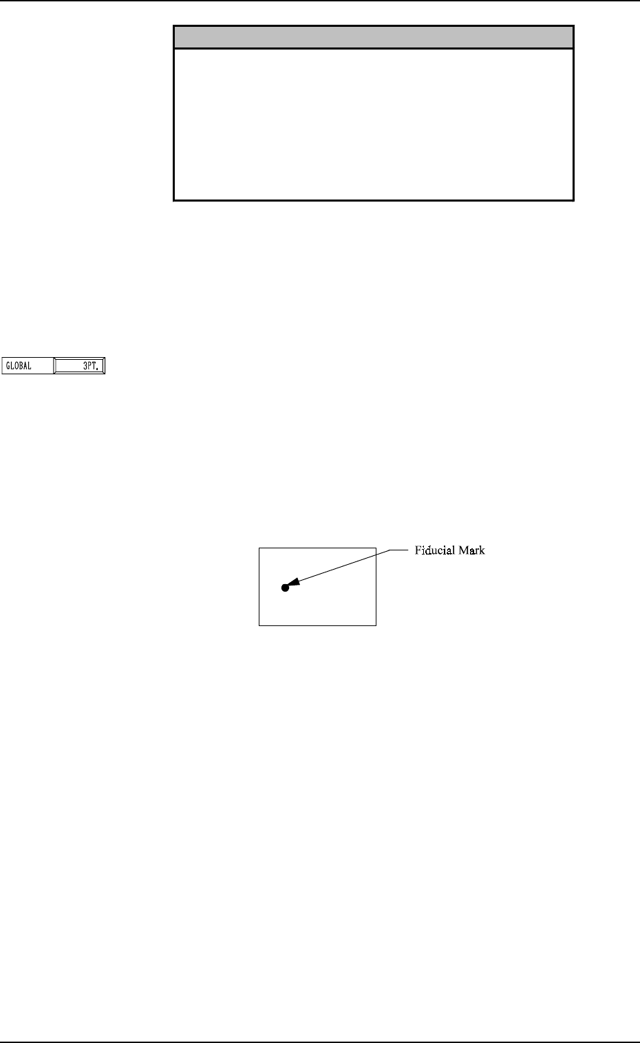
P.E.C. RECOGNITION MODE GLOBAL
Set one of the following options to set the number of recogni-
tion points for the P.E.C. global recognition function.
“OFF”
“1PT.”
“2PT.”
“3PT.”
[1-Point Recognition]
2. Pattern Program
Reference
•
When “AFTER PU” is set in the data box, a component is
picked up and the component recognition is performed on the
component while the P.C.B. is being transferred to the P.C.B.
positioning section.
Since the component is already picked up, it can be placed
soon after the component and P.E.C. recognition functions are
performed. Because the loss time (waiting time) decreases,
there is an effect to shorten the time to finish a P.C.B.
Fig. 2.15
• Only the X and Y elements are corrected. The θ element
(expansion, etc.) is not corrected.
9910-001 2-20 Tg0247-PM-PM
0004-002 2-21 Tg0247-PM-PM
2. Pattern Program
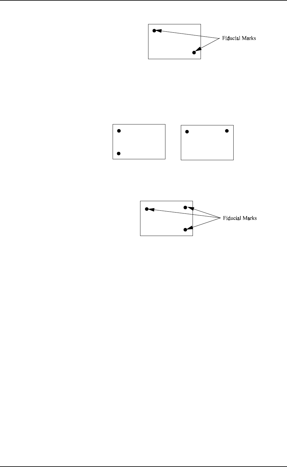
[2-Point Recognition]
Fig. 2.16
• Specify fiducial mark positions so that one fiducial mark is
kept as diagonally away from the other as possible.
Note: Avoid fiducial mark positions where the X and Y ele-
ments are the same. See Fig. 2.17 below.
Fig. 2.17
[3-Point Recognition]
Fig. 2.18
• Specify fiducial mark positions so that the triangle area
formed by connecting the three points (three fiducial marks)
becomes as large as possible.
Note: When any two of the three fiducial marks are desig-
nated to be positioned as close as possible to each other,
the results of the correction will be almost the same as
“2-Point Recognition” because the bend, expansion,
etc., of P.C.B. are detected as even occupants of the X
and Y elements.
In other words, the bend, expansion, etc., of P.C.B. oc-
cupying the X and Y elements unevenly will cause
wrong correction result.