2OM-1064-002.pdf - 第191页
Note: The center of the mark is the reference point. 3. FEEDER (A) OFFSET and FEEDER (B) OFFSET Displays 9910-001 5-21 Tg0247-PM-PM L (+) Pick-Up Reference Level Nozzle TRAY FEEDER-L X(+) Y(+) X(+) X(+) X(+) Y(+) Y(+) Y(…
FEEDER (B) OFFSET X (mm), Y (mm) (Multi-Layer Tray
Feeder) (Option)
The set parameters are used to correct the variation for each
block of steps, based on the PL-XY coordinate system.
Enter the positional deviations from the pick-up position for each
individual pallets, including the traverse pullout position (multi-layer
tray offset), such that components can be picked up at their centers.
When the automatic feeder axis adjustment mode is enabled for the
pick-up position, this data is updated automatically as to pick up the
component center based on the results of the component recognition
for the component picked up during automatic operation.
Refer to “5.1 AUTOMATIC FEEDER AXIS ADJUSTMENT
MODE Display of Section 3 in Volume 1” for the detailed
information on how to set the automatic feeder axis adjust-
ment mode.
Ref.: The manual alignment teaching operation is possible.
9910-001 5-20 Tg0247-PM-PM
3. FEEDER (A) OFFSET and FEEDER (B) OFFSET Displays
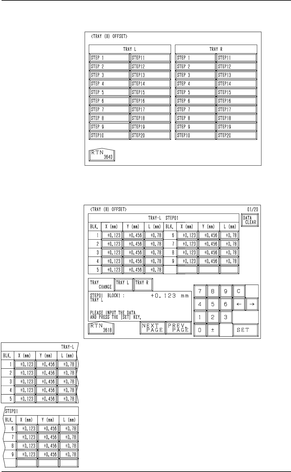
When the [TRAY] key is pressed at the “FEEDER (B) OFFSET” dis-
play (Fig. 5.13), the following display appears on the screen. (Op-
tion)
When one of the [STEP X] keys (the keys used to designate the
step to be set) is pressed at the display (Fig. 5.20), the following
display appears on the screen.
Fig. 5.20
Fig. 5.21
Note: The center of the mark is the reference point.
3. FEEDER (A) OFFSET and FEEDER (B) OFFSET Displays
9910-001 5-21 Tg0247-PM-PM
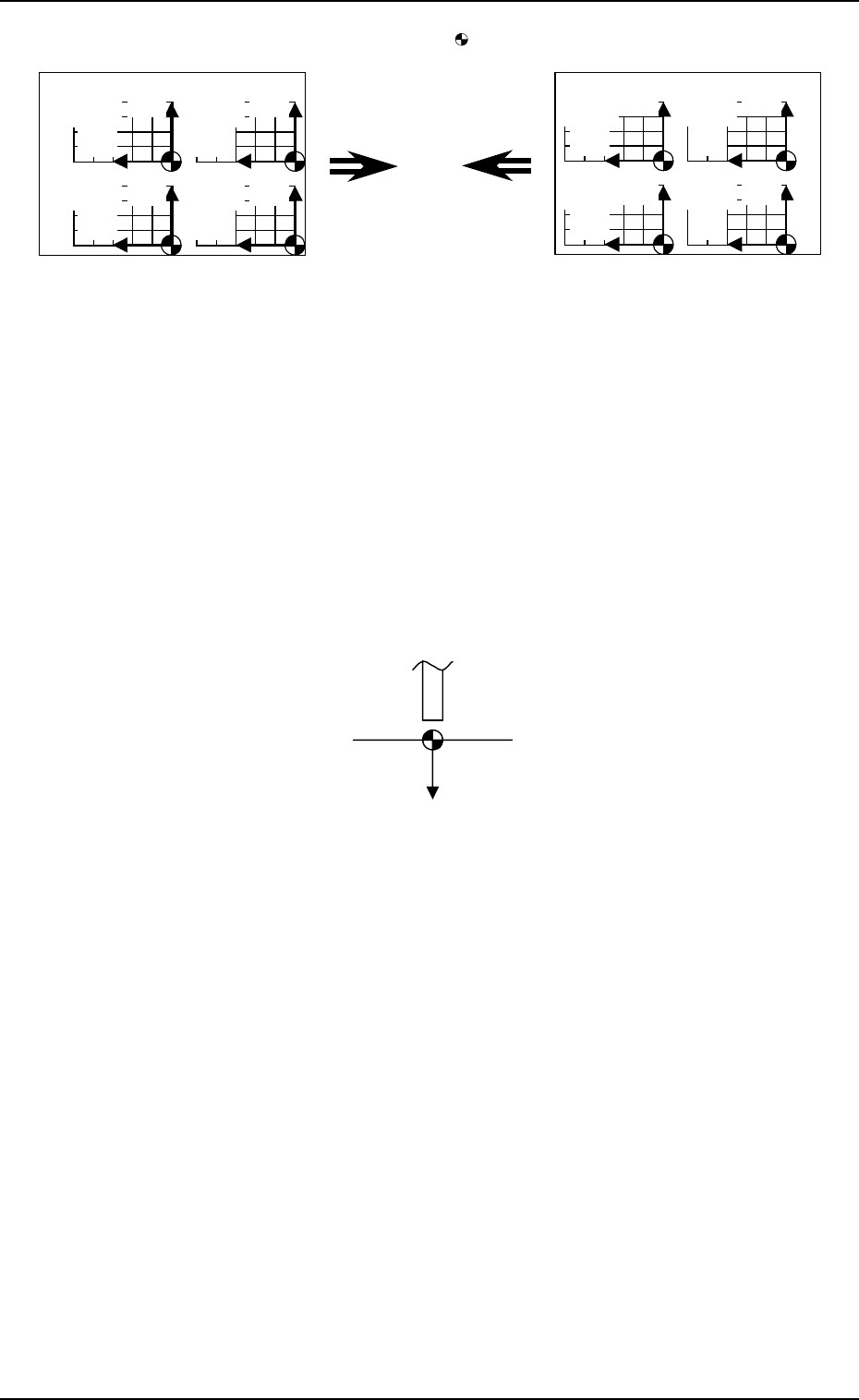
L (+)
Pick-Up Reference Level
Nozzle
TRAY FEEDER-L
X(+)
Y(+)
X(+)
X(+) X(+)
Y(+)
Y(+) Y(+)
Block 4
TRAY FEEDER-R
X(+)
Y(+)
X(+)
X(+) X(+)
Y(+)
Y(+) Y(+)
Block 3
Block 2
Block 1
Pallet Drawing
Direction
Pallet Drawing
Direction
Block 4
Block 3
Block 2
Block 1
Fig. 5.22
When offset parameters are set with a plus (+) sign, the com-
ponent pick-up directions (position) are changed to “X (+)”
and “Y (+)” shown in the above figure.
FEEDER (B) OFFSET L (mm) (Multi-Layer Tray Feeder)
(Option)
The set parameters are used to correct the variation in the pick-
up height of each block of steps.
These parameters are reflected on the descending stroke of the
head required to pick up a component.
Note: The automatic feeder axis adjustment mode cannot be
used for this data.
Fig. 5.23
When a value is entered with a plus (+) sign, the pick-up height
is changed to “L (+)” shown in the figure above, concluding
that the descending stroke has increased.
When the [DATA CLEAR] key is pressed, a display appears, en-
abling you to clear the data.
Whenever a tray is replaced with another one, it is recommended
that the feeder (B) offset data should be cleared.
When parameters are not set correctly for each individual blocks,
components may not be picked up successfully because the feeder
(B) offset data contains the offset values for the trays of the blocks
in each pallet.
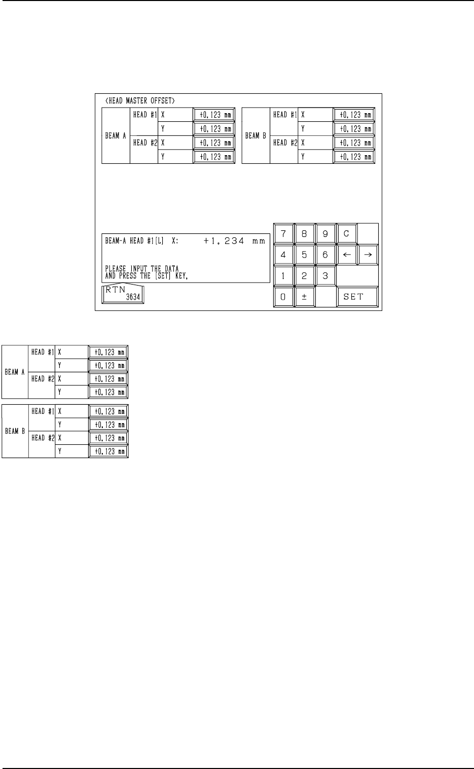
Fig. 5.24
BEAM A/BEAM B HEAD #1/HEAD #2 X (Horizontal), Y (Ver-
tical)
This offset data is used to correct the positional deviation
(placement coordinates) caused due to the deviation of
straightness (skew) of each individual head up/down axis
guides. The set parameters are added to the amount of beam
movement (travel) for component placement.
Note: The offset values are not reflected on the automatic
teaching operation.
4. HEAD MASTER OFFSET Display
When the [HEAD MASTER OFFSET] key is pressed at the “OFFSET DATA”
display, the following display appears on the screen.
9910-001 5-22 Tg0247-PM-PM
4. HEAD MASTER OFFSET Display