2OM-1064-002.pdf - 第242页
ECCENTRIC DIST ANCE X (Horizontal) and Y (V ertical) In the case of the special nozzle whose tip is manufactured eccentrically from the head rotational center , set the eccentric- ity (distances) separately in the “X” an…
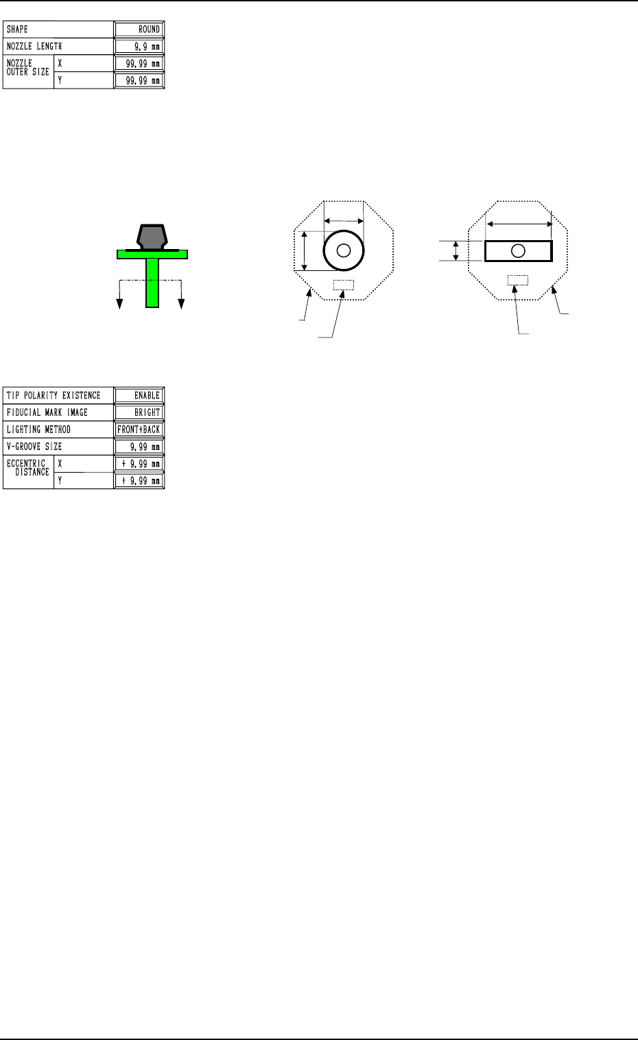
Fig. 8.4 Sectional View A-A’
TIP POLARITY EXISTENCE
Set “ENABLE” or “DISABLE” in the data box to specify
whether or not the polarity exists in the shape of the nozzle
tip.
ENABLE : Special Nozzle with Polarity (asymmetrical)
DISABLE : Round Nozzle or the like without Polarity
FIDUCIAL MARK IMAGE
Specify how (bright or dark) the image of the nozzle tip is
captured in the front lighting system.
The set parameter is required for nozzle masking in the front
lighting recognition.
“BRIGHT” or “DARK”
In normal cases, set “BRIGHT” in the data box.
LIGHTING METHOD
Determine in which lighting system (“BACK”, “FRONT”, or
“FRONT+BACK”) the nozzle can be used.
“BACK”
“FRONT”
“FRONT+BACK”
Ref.: “FRONT” must be selected for such a nozzle that the
image of the area other than the nozzle tip appears dark
in the back lighting system.
“BACK” must be selected for such a nozzle that the
image of the area other than the nozzle tip appears
bright in the front lighting system.
“FRONT+BACK” must be selected when “ROUND”
is set in the “SHAPE” data box.
V-GROOVE SIZE: Reserved Data
When the V-grooved nozzle is used for cylindrical compo-
nents, set the size of the V groove in the data box.
• Data Input Range
0 to 99.99 mm
In the case of the nozzle without a V groove, set “0” (zero) in
the data box.
NOZZLE OUTER SIZE X (Horizontal) and Y (Vertical)
Set the outer dimensions of the nozzle tip section.
In the case of “ROUND”, set the same dimensions for “X”
and “Y”.
In the case of “RECTANGLE”, set the dimension of the longer
side in the “X” data box and the dimension of the shorter one
in the “Y” data box.
• Data Input Range
X: 0 to 99.99
Y: 0 to 99.99
2. NOZZLE TYPE DATA Display
X
Y
Y
X
Imprinted Nozzle ID
Diffusion Plate
Imprinted Nozzle ID
Diffusion Plate
A
’
A
0004-002 8-5 Tg0247-PM-PM
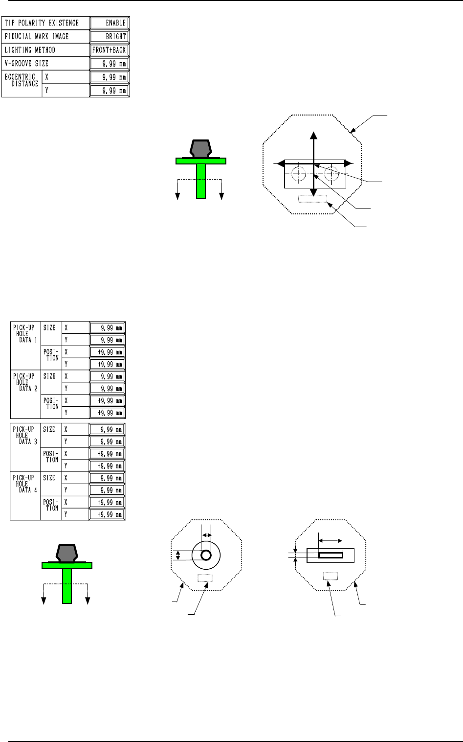
ECCENTRIC DISTANCE X (Horizontal) and Y (Vertical)
In the case of the special nozzle whose tip is manufactured
eccentrically from the head rotational center, set the eccentric-
ity (distances) separately in the “X” and “Y” data boxes.
• Data Input Range
0 to 99.99 mm
Specify X and Y as shown in Fig. 8.5.
Fig. 8.5 Sectional View A-A’
(Eccentric Designation: X = 0 and Y = Minus)
Set the data values (X, Y) as “0, 0” for a standard nozzle.
Second Page
PICK-UP HOLE DATA 1, 2, 3, 4
SIZE X (Horizontal), Y (Vertical)
Set the dimensions of the nozzle pick-up hole in the data boxes.
In the case of “ROUND”, set the same dimensions for “X”
and “Y”.
Set X and Y as shown in Fig. 8.5 in the case of a rectangle.
• Data Input Range
X: 0 to 99.99
Y: 0 to 99.99
Fig. 8.6 Sectional View A-A’
2. NOZZLE TYPE DATA Display
A
’
A
X
Y
Y
X
Imprinted Nozzle ID
Diffusion Plate
Imprinted Nozzle ID
Diffusion Plate
A
’
A
9910-001 8-6 Tg0247-PM-PM
X(+)
Y(+)
Nozzle Center
Diffusion Plate
Imprinted Nozzle ID
Nozzle Rotational Center
X(-)
Y(-)
2. NOZZLE TYPE DATA Display
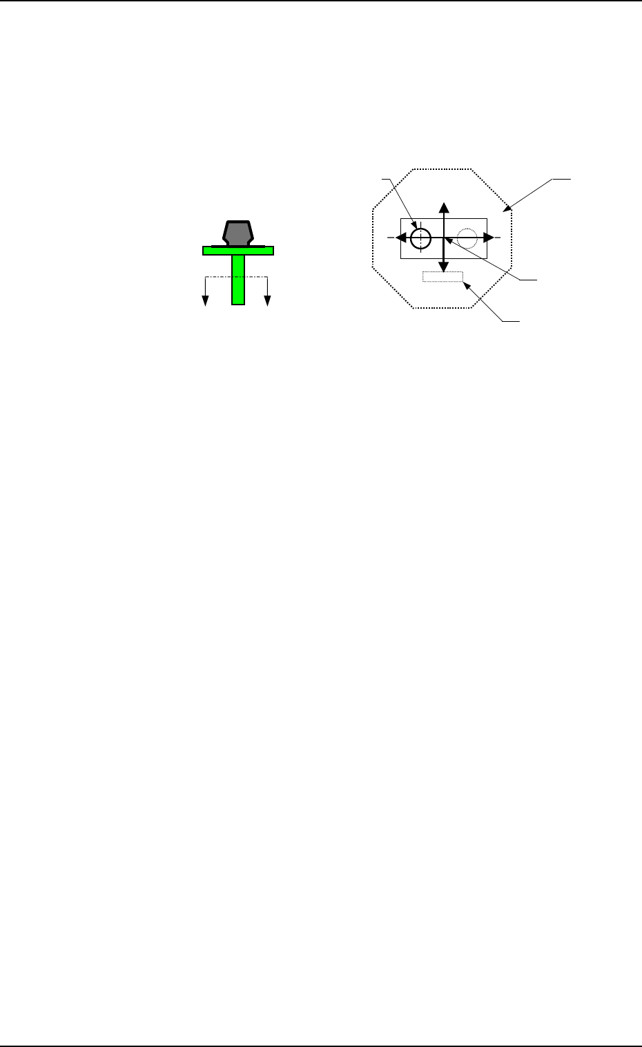
POSITION X (Horizontal), Y (Vertical)
The set parameters are used to specify the center position of
Pick-Up Hole (1) based on the nozzle center.
• Data Input Range
X: 99.99 to +99.99
Y: 99.99 to +99.99
Set X and Y as shown in Fig. 8.7.
A
’
A
Fig. 8.7 Sectional View A-A’
When no relevant hole is found, set the data values (X, Y) as
“0, 0”.
Up to 4 pieces of pick-up holes can be specified.
Operation
• Press the data key to be edited and use the ten-key pad or the
option keys to enter a parameter. Then, press the [SET] key.
• When the [RTN] key is pressed, the “NOZZLE TYPE DATA
SAVE MODE” display appears on the screen.
Note: When a special nozzle is attached, the nozzle type data
must be registered as new one.
9910-001 8-7 Tg0247-PM-PM
X(+)
Y(+)
Pick-Up Hole (1)
Nozzle Center
Diffusion Plate
Imprinted Nozzle ID
X(-)
Y(-)