2OM-1064-002.pdf - 第168页
Latest Image Old Image Up to 16 Images Retainable (Resolution: 25%) Up to 4 Images Retainable (Resolution: 50%) 1 Image Retainable (Resolution: 100%) 9910-001 4-6 Tg0247-PM-PM 3. RECOGNITION ERROR IMAGE SA VE SET-UP Disp…
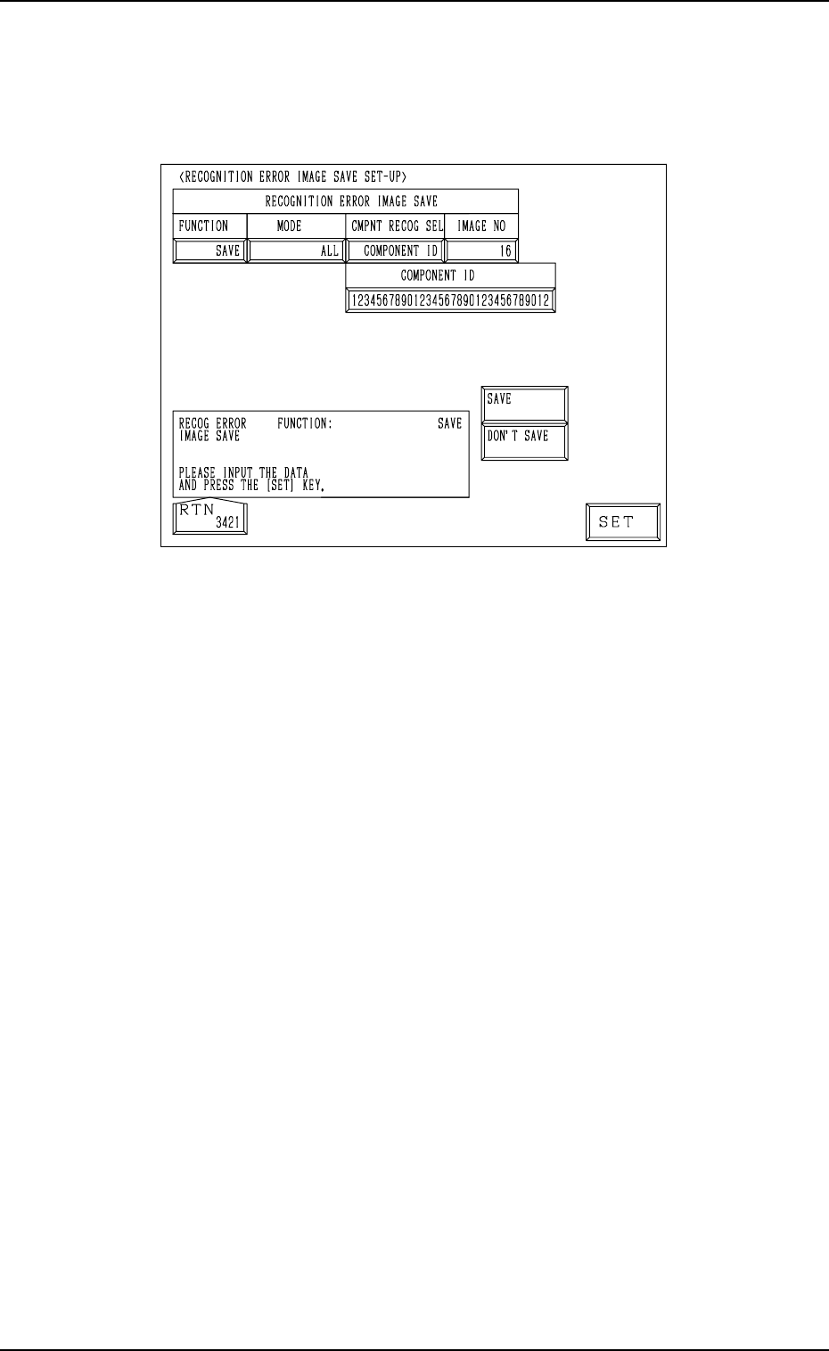
3. RECOGNITION ERROR IMAGE SAVE SET-UP Display
3. RECOGNITION ERROR IMAGE SAVE SET-UP Display
When the [RECOG ERR IMAGE SAVE SET-UP] key is pressed at the “AUTO
OPERATION SET-UP” display, the following display appears on the screen.
9910-001 4-5 Tg0247-PM-PM
Fig. 4.3
Set a parameter for each label (MODE, CMPNT RECOG SEL, IMAGE NO)
to analyze the cause of a recognition error in comparison with the error image
on the monitor.
When “SAVE” is set in the “FUNCTION” data box, the image which matches
the save mode (parameters set for “MODE” and “CMPNT RECOG SEL” dur-
ing operation) is stored in memory.
• Error images stored in memory can be saved on a floppy disk and sent to us
for error analysis.
Refer to “4.1 Error Image Save Function of Section 3 in Volume 4” for
details.
FUNCTION : “SAVE” or “DON’T SAVE”
MODE : “ALL”, “CMPNT RECOG”, “P.E.C. RECOG”
CMPNT RECOG SEL:
“OFF”, “CAMERA NO”, “COMPONENT ID”, “FEEDER NO”,
“HEAD NO”, or “NOZZLE NO”
CAMERA NO : The camera No. must be specified.
COMPONENT ID : The component ID must be specified.
FEEDER NO : The feeder No. must be specified.
HEAD NO : The head No. must be specified.
NOZZLE NO : The nozzle ID must be specified.
Note: As for “CMPNT RECOG SEL”, the set parameter is valid only
for those related to component recognition errors.
Setting of “RECOGNITION ERROR IMAGE SAVE” for “P.E.C.
RECOG.2 is unconditional.
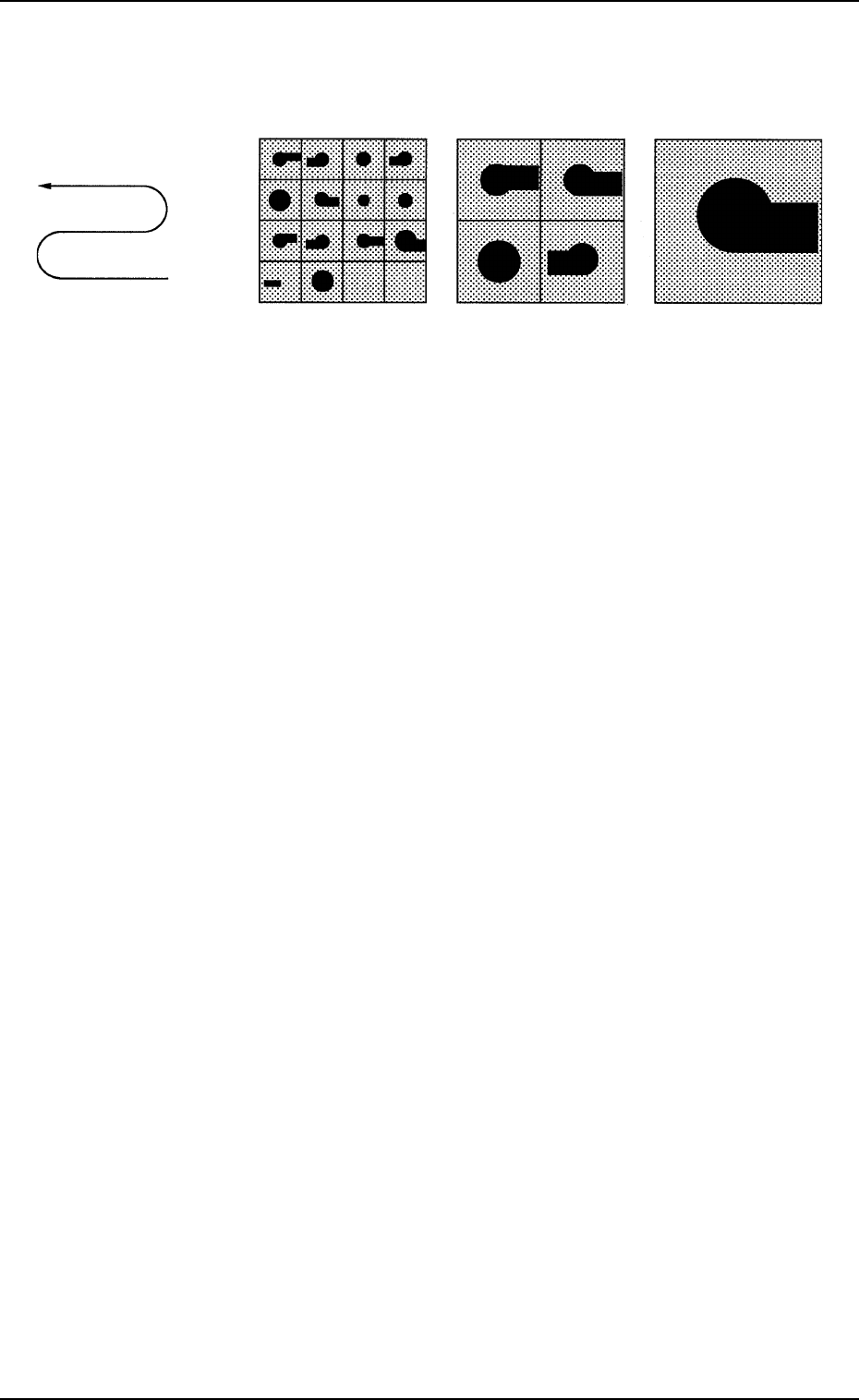
Latest Image
Old Image
Up to 16 Images
Retainable
(Resolution: 25%)
Up to 4 Images
Retainable
(Resolution: 50%)
1 Image Retainable
(Resolution: 100%)
9910-001 4-6 Tg0247-PM-PM
3. RECOGNITION ERROR IMAGE SAVE SET-UP Display
IMAGE NO: [16] (25% Resolution)
[ 4] (50% Resolution)
[ 1] (100% Resolution)
Notes: (a) The image data stored in memory is cleared when the parameter in
the “IMAGE NO” data box is changed, the recalled recognition
error data is deleted, or the power switch of the machine is turned
off.
(b) When “16” or “4” is set in the “IMAGE NO” data box in the case
of the divided recognition, only the error-caused image data is
stored in memory.
(For example, when an error is caused in the component during
the fifth recognition operation (out of nine recognition operations),
only the data of the image captured during the fifth recognition
operation is stored in memory at a resolution of 25% or 50%.)
When “1” is set in the “IMAGE NO” data box, up to three images
are stored in memory at a resolution of 100%.
(For example, when an error is caused in the component during
the fifth recognition operation (out of nine recognition operations),
the data of the images captured during the third, fourth, and fifth
recognition operations is stored in memory at a resolution of
100%.)
(c) It is required to save error images (resolution: 100%) for detailed
analysis (investigation and analysis on maker side) of recognition
errors. That is, “1” must be set in the “IMAGE NO” data box at
the “RECOGNITION ERROR IMAGE SAVE SET-UP” display.
4. AUTOMATIC TUNING Display
When the [AUTOMATIC TUNING] key is pressed at the “AUTO OPERA-
TION SET-UP” display, the following display appears on the screen.
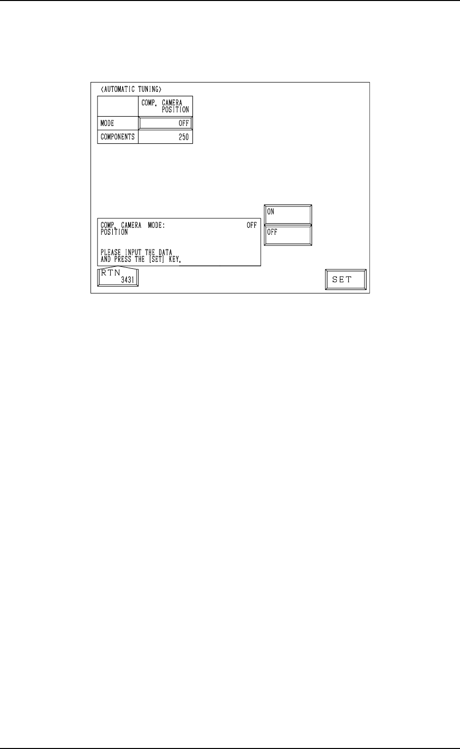
4. AUTOMATIC TUNING Display
Fig. 4.4
The following parameters are used to periodically adjust minute deviation
(caused due to the thermal expansion of the ball screw) in the position of each
section during automatic operation.
COMP. CAMERA POSITION
MODE: “ON” or “OFF”
“ON” or “OFF” can be selected to determine whether or not the compo-
nent recognition camera position should be corrected periodically ac-
cording to the number of components to be placed.
In normal cases, it is recommended that “ON” should be set in the data
box.
Note: When no checker marks are used, set “OFF” in the data box.
COMPONENTS
[0] : No automatic correction operation is performed for each
number of components to be placed.
[1 to 250] : Correction is made according to the specified number of
components to be placed. (Beam-Based Management)
When “ON” is set in the “MODE” data box, the correc-
tive actions take place automatically before component
recognition operation after the P.C.B. is transferred to the
P.C.B. positioning section.
When the number of components (components to be placed
on a production P.C.B.) per beam is smaller than the set
number of components, the corrective actions do not take
place in the middle of placement operation.
Because the internal counter for interval monitoring is
cleared through the above-described corrective actions (the
actions which take place during P.C.B. positioning), no
corrective actions take place in compliance with the num-
ber of components to be placed on several P.C.B.’s.
0004-002 4-7 Tg0247-PM-PM