2OM-1064-002.pdf - 第68页
9910-001 2-56 Tg0247-PM-PM 2. Pattern Program *12 [STEP COPY] Key Pressing this key opens a display which makes it possible to copy the selected step No. to another step. Refer to “4.6.4 Special Operation (Step Copy) for…
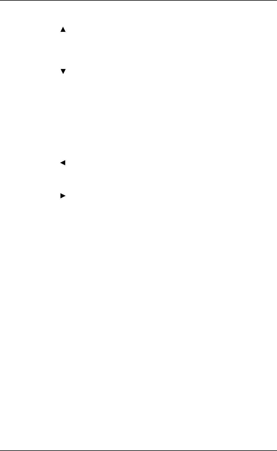
*1 Move the line cursor (blue) by pressing scroll arrow keys *2 and *3.
*2 [ ] Key
This key is called “Scroll Up Arrow”.
When the line cursor is located at the top and this key is pressed, step Nos.
scroll up (Smaller Nos. appear one by one.).
*3 [ ] Key
This key is called “Scroll Down Arrow”.
When the line cursor is located at the bottom and this key is pressed, step
Nos. scroll down (Larger Nos. appear one by one.).
*4 [NEXT PAGE] Key
Pressing this key opens the next page if one exists.
*5 [PREV. PAGE] Key
Pressing this key opens the previous page if one exists.
*6 [ ] Key
Pressing this key shifts the “COMPONENT ID” field horizontally to the
left, enabling to view the first part of component IDs.
*7 [ ] Key
Pressing this key shifts the “COMPONENT ID” field horizontally to the
right, enabling to view the comments.
*8 [STEP DELETE] Key
When the line cursor is moved to the step No. to be deleted and this key is
pressed, the parameters related to the step No. is deleted.
(The line at the line cursor position is deleted and the subsequent data is
shifted up.)
*9 [STEP INSERT] Key
When this key is pressed, a blank step of 1 pitch is inserted (registered) in
the step No. at the line cursor position.
*10 [STEP JUMP] Key
Pressing this key opens a display which shows the lines of step data start-
ing with the selected step No.
Refer to “4.6.3 Special Operation (Step Jump) for Placement Data of Sec-
tion 2” for details.
*11 [STEP MOVE] Key
Pressing this key opens a display which makes it possible to move from
the selected step No. to another step.
Refer to “4.6.5 Special Operation (Step Move) for Placement Data of Sec-
tion 2” for details.
9910-001 2-55 Tg0247-PM-PM
2. Pattern Program
9910-001 2-56 Tg0247-PM-PM
2. Pattern Program
*12 [STEP COPY] Key
Pressing this key opens a display which makes it possible to copy the
selected step No. to another step.
Refer to “4.6.4 Special Operation (Step Copy) for Placement Data of Sec-
tion 2” for details.
*13 [DATA EDIT] Key
Pressing this key opens the data edit display.
Refer to “4.6.6 Editing of Placement Data of Section 2” for details.
*14 [OFFSET DATA EDIT] Key
Pressing this key opens the “PLACEMENT DATA (O) U01” display.
*15 [VISION DATA EDIT] Key
Pressing this key opens the “PLACEMENT DATA (V) U01” display.
Description of Parameters
P-NO
This shows the step Nos. of component placement data.
(The step “P-0000” always appears on the screen.)
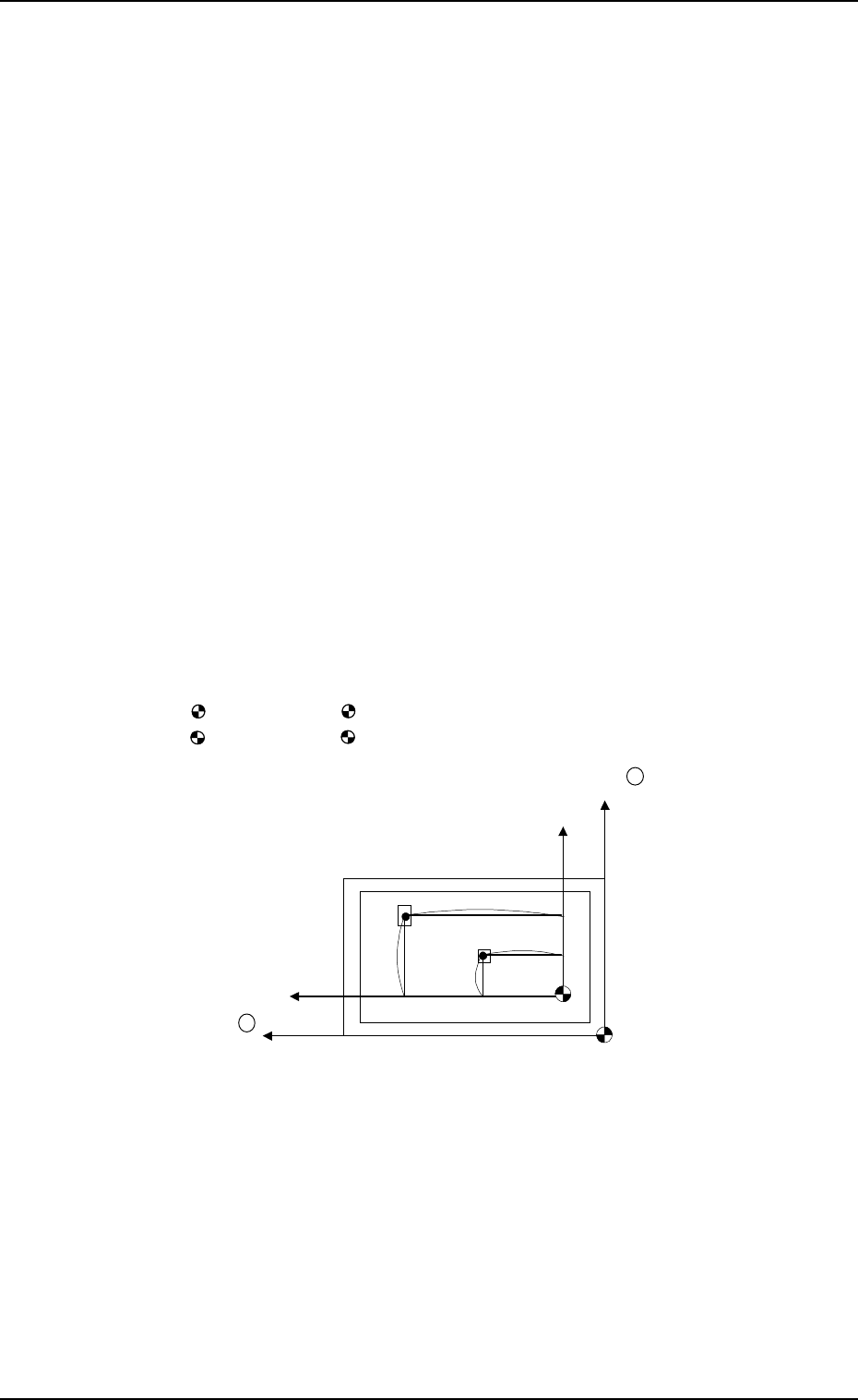
X (mm) and Y (mm)
Set component placement coordinates X and Y.
• Parameters can be entered using the absolute values (no signs) of the
distance from the placement data reference. (P-0001 to )
: The center of mark is P.C.B. positioning reference.
: The center of mark is Pattern Origin.
Y +
X +
(P.C.B.)
No (Placement Data Reference)
Po (P.C.B. Positioning Reference)
X
1
Y
1
X
2
Y
2
• Offset values in placement coordinate data must be entered in the text field
of step P-0000 labeled “X (mm)” and “Y (mm)”.
The offset values can be entered in the range of “-99.99 to +99.99 (mm)”
with + or - sign.
• Placement position can be specified by the placement coordinates data where
both pattern program offset (operation data) and X & Y parameters in step
P-0000 are added to the P.C.B. positioning reference (Po).
9910-001 2-57 Tg0247-PM-PM
2. Pattern Program
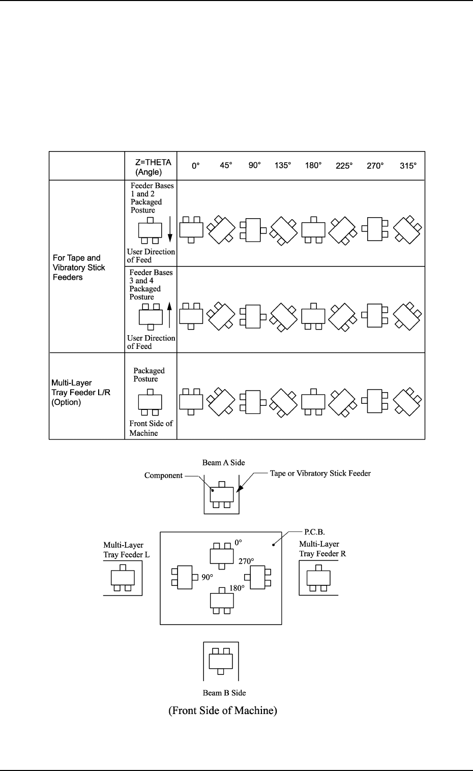
Z=THETA (Angle)
Set component placement angle data Z.
• Data Input Range: 0°00´ to 359°59´
• Offset value must be entered as placement angle offset in the data field
of step P-0000 labeled “Z=THETA”.
The offset values can be entered in the range “-99°99´ to +99°99´ ” with
+ or - sign.
Note: The following shows the placement angles changed from the pack-
aged posture of a component.